


G4 Owner’s Manual – 15a – Trap System Packing Instructions

The Mirage TRAP SYSTEM™ is a unique approach to how a Main Assisted Reserve Deployment (MARD) system functions. The Trap System design is simple, reliable, and rigger friendly.
The TRAP SYSTEM™ is not attached to the reserve bridle in any way until needed. Only when the main parachute is cutaway does the Trap engage and aid in deployment of the reserve parachute. If the ripcord is pulled, or an AAD deploys the reserve, there is no mechanical device that must first detach to allow your reserve to deploy normally.
The TRAP SYSTEM™ includes these parts:
- The Trap and the Trap Door (cover), which are sewn to the No. 1 pilot chute kicker flap of the Mirage reserve container;
- A red RSL lanyard with a Trap Line installed;
- A modified reserve bridle which is simply folded and sewn for insertion into the elastic keeper;
- A pair of Mirage Systems, Inc. main risers with a factory installed RSL ring.
Caution
Use ONLY main risers made by Mirage Systems, Inc., with a factory installed RSL ring!
The TRAP SYSTEM™ has not been tested using risers built by other manufacturers.
Use ONLY genuine TRAP SYSTEM™ parts available from Mirage Systems, Inc.
The use of locally modified reserve freebag bridles or locally made replacement RSL lanyards and Trap Lines is not authorized!
The following instructions should be followed closely to properly assemble and pack the TRAP SYSTEM™.
If you have questions, contact Mirage Systems, Inc.
Assembly
1. Fold the RSL together, mating the velcro strips, and insert under yoke with snap shackle tab facing inward.
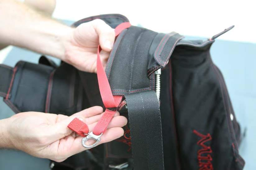
2. Route the RSL over the yoke toward the reserve container and place under the lip of the RSL retainer (a half-twist outward is helpful).
WARNING
DO NOT ROUTE THE TRAP RSL OR TRAP LINE AROUND OR THROUGH THE RESERVE RISERS. THE RISERS MUST BE ABLE TO FULLY EXTEND FOR PACKING WITHOUT DISTURBING THE TRAP RSL.
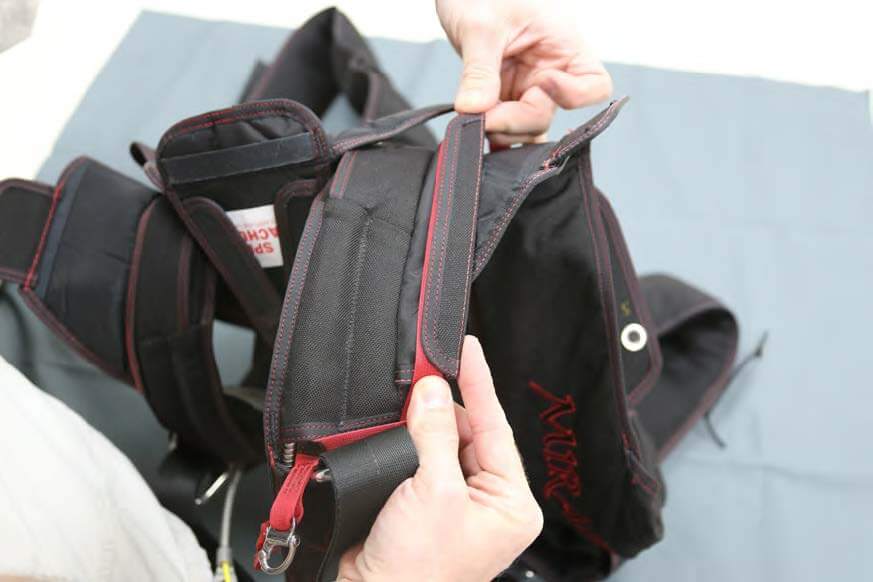
3. Fold the retainer and RSL onto the yoke, removing any twist in the RSL.
The label on the RSL should now be facing up.
4. Pull the Trap Line through the loop on the end, forming a cinch. The end loop has red stitching.
Helpful Hint
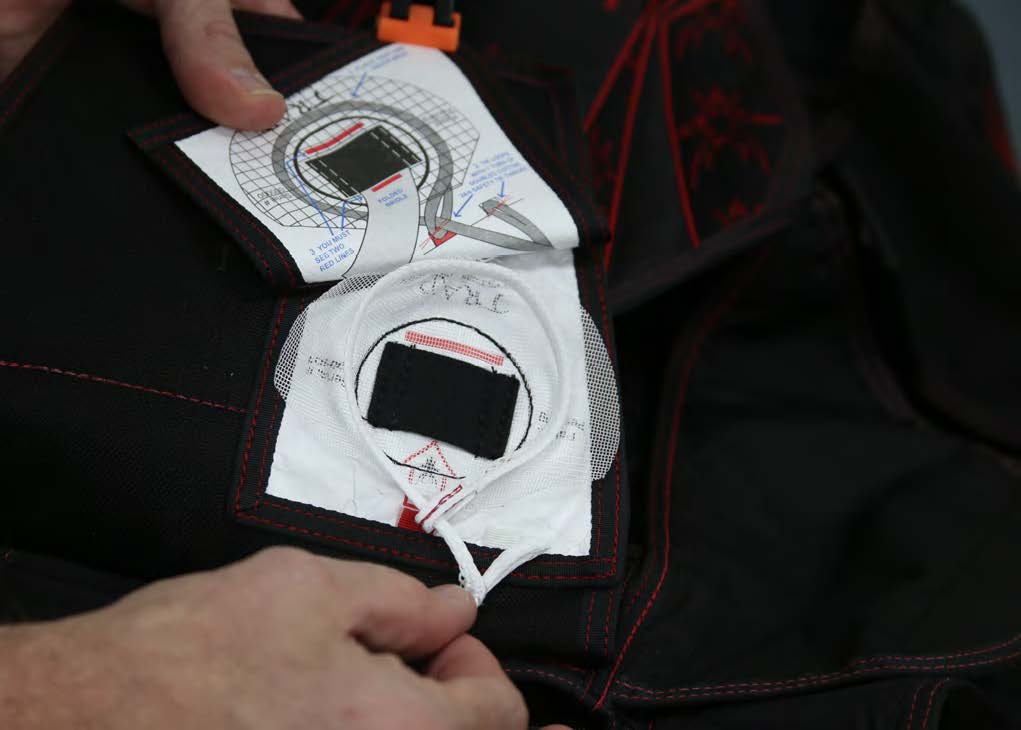
A clamp may be used to keep the Trap Door folded out of the way during the next steps.
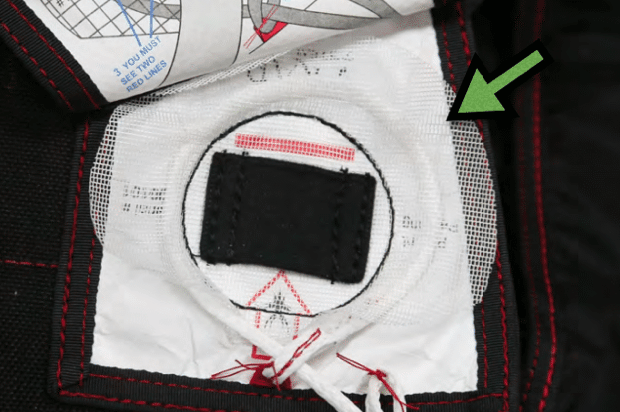
5. Place the Trap Line on top of the mesh as illustrated on the inside of the Trap Door.
6. Thread a doubled length of cotton 24/4 safety tie thread through the end loop on the Trap Line, and the red tab on the Trap.
Do not use a needle to pierce the end loop or Trap Line.
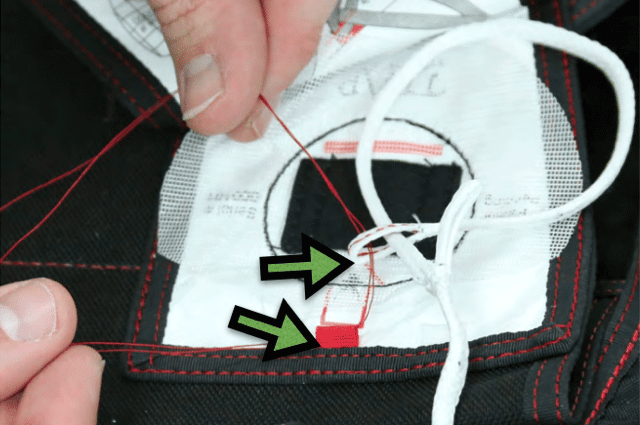
7. Tie the end loop and red tab together with a surgeon’s knot and a square knot.
Cut thread leaving 1/4”– 1/2” (.635cm – 1.27cm) tails.
Make sure that Trap Line is free to slide through the loop after the knot is tied.
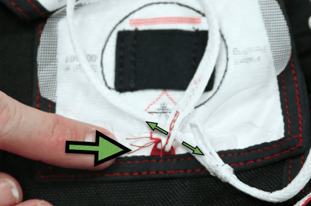
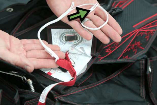
8. Tie the white loop on the Trap Line and the white tab on the Trap together using doubled cotton 24/4 thread.
Cut thread leaving 1/4” – 1/2” (.635cm – 1.27cm) tails.
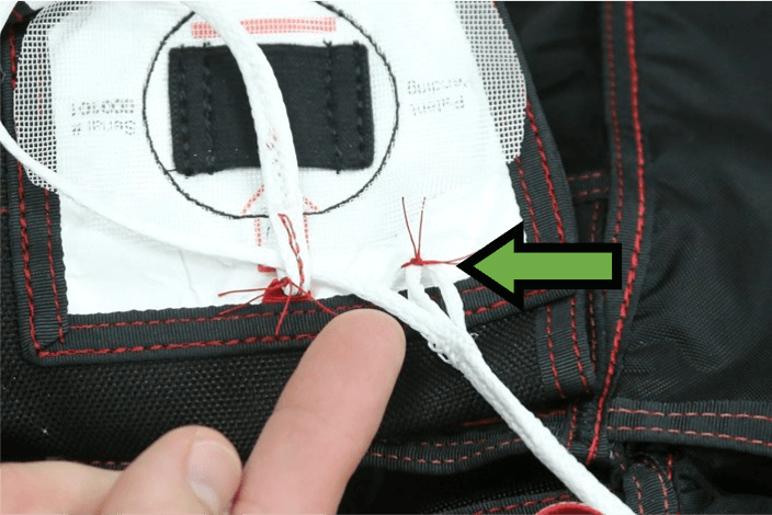
9. IMPORTANT.
Place the Trap Line UNDER the mesh, as shown. The loop should be evenly distributed.
Smooth the mesh.
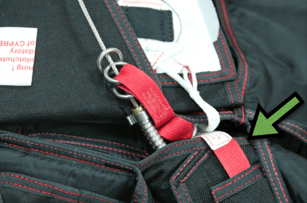
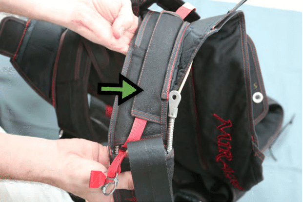
10. With the loop for Trap Line on the RSL facing up, route the ripcord cable through first guide ring on No. 6 reserve pin flap, the ring on the RSL, then the second guide ring on the No. 6 reserve pin flap, as shown.
Make sure that the RSL and Trap Line are not twisted.
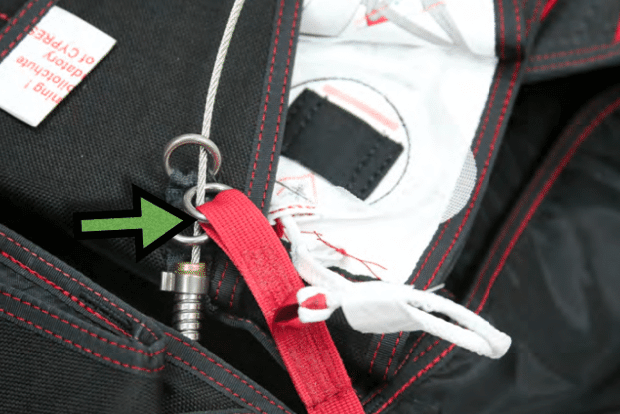
11. Neatly tuck excess RSL and Trap Line between the reserve container and the back pad, as shown. Remove the clamp (if used).