


Mirage Owner's Manual : G4 / G4.1 / G4.2 / G4.3
1 – Table of Contents
2 – Introduction
3 – Warning
4 – Operating Limits
5 – Service Life
6 – Service Bulletins
7 – Rigging Requirements
8 – Authorized Components
9 – Installing An Automatic Activation Device (AAD)
10 – Installing The Reserve Parachute Canopy
11 – Installing The Reserve Deployment Bag And Pilot Chute
12 – Installing A Reserve Closing Loop
13 – Installing A Reserve Static Line (RSL)
14 – Packing The Reserve Parachute
15 – Trap System Packing Instructions
16 – Installing The Main Parachute Canopy And Risers
17 – Installing The Main Deployment Bag And Pilot Chute
18 – Packing The Main Parachute
18.1- Packing A Split Deployment Bag
18.2 – Packing A Semi-Stowless Deployment Bag
19 – Closing The Main Container
19.1 – Folding The Main Pilot Chute
20 – Pull Out Pilot Chute Packing Instructions
21 – Maintaining Your Mirage – Inspection
21 – Maintaining Your Mirage – Cleaning
21 – Maintaining Your Mirage – 3 Ring Release Maintenance
21 – Maintaining Your Mirage – Installing Replacement Cutaway Handle
21 – Maintaining Your Mirage – Repairs
22 – User Instructions
23 – Installing Swoop & Sit Fly Belly Bands
24 – Installing Main Risers With Large Swoop Loops
9/28/2018
2 – Introduction
Congratulations on your purchase of a Mirage Harness and Container System!
We feel that the Mirage is the finest harness and container system available today and hope that you will agree. With proper use and care, it should provide many years of service. It is our sincere wish that your Mirage exceeds your expectations.
This manual is intended as a guide for the use and care of your Mirage, but is not a substitute for proper training in sport parachuting (skydiving) techniques or emergency procedures. Before using your Mirage, seek professional instruction from a qualified instructor familiar with its features.
Assembly and packing instructions for the reserve parachute are included as a guide for use by an appropriately rated senior or master parachute rigger, or foreign equivalent.
If you have any questions about your new Mirage, please contact us.
MIRAGE SYSTEMS, INC.
P.O. BOX 820
DELAND, FL 32721-0820
386-740-9222
rigging@miragesys.com
4/28/2016
3 – Warning
WARNING!
SPORT PARACHUTING (SKYDIVING) IS A HAZARDOUS ACTIVITY WITH INHERENT RISKS THAT CAN RESULT IN INJURY OR DEATH!
BEFORE USING A MIRAGE HARNESS AND CONTAINER ASSEMBLY:
Read and understand this warning.
Read and understand the contents of this manual.
Complete a course of instruction in the proper use and functioning of your Mirage.
NOTHING ABOUT SPORT PARACHUTING (SKYDIVING) SHOULD BE CONSIDERED “SAFE”.
Training, current experience, and properly maintained equipment may lessen the risks involved, but all risk cannot be eliminated.
You can be injured or killed even if your equipment works properly and you do everything right.
IF YOU ARE NOT WILLING TO ACCEPT ALL OF THE RISKS INVOLVED IN SPORT PARACHUTING (SKYDIVING), YOU SHOULD NOT ATTEMPT TO PARTICIPATE.
Parachutes can, and do, malfunction even if they are properly designed, tested, manufactured, assembled, packed, maintained and used.
If you are not prepared to accept the possibility that your Mirage, or any of its components, may malfunction and possibly cause you to be injured or killed,
you should reconsider participation in sport parachuting (skydiving).
If you use a Mirage, or allow others to use your Mirage, you are acknowledging the fact that sport parachuting (skydiving) is a hazardous activity and that
there is a possibility that your Mirage and any of its installed components may malfunction, resulting in the injury or death of the user.
4/28/2016
4 – Operating Limits
PARACHUTES, LIKE AIRPLANES, HAVE OPERATING LIMITS THAT HAVE BEEN ESTABLISHED THROUGH TESTING.
Mirage parachute harnesses are approved for manufacture by the FAA under Technical Standard Order (TSO) C-23b and the “Low Speed Category” of National Aerospace Standard (NAS)-804.
As required by NAS-804, a series of static Line drop tests were made at the following airspeeds and payload weights to subject the harness to the required minimum of 3000 pounds of shock load. Mirage harnesses passed testing to these standards.
- 100 MPH……..750 LBS.
- 125 MPH……..525 LBS.
- (130 kts) 150 MPH……..375 LBS. (170 kg)
- 175 MPH……..300 LBS.
- 200 MPH……..235 LBS.
- 225 MPH……..200 LBS.
NAS-804 sets the maximum operating speed of a “Low Speed Parachute” at 150 MPH, even though the assembly could withstand higher speeds at a lower weight, or higher weights at lower speeds, and still remain within the tested range.
To lower the risk of equipment failure, injury, or death, never exceed 150 MPH (130 kts) when opening the main or reserve parachutes of your Mirage.
Mirage harness and container systems are required to be labeled “LOW SPEED PARACHUTE LIMITED TO USE IN AIRPLANE UNDER 150 MPH”. This label is located inside the reserve container pin cover flap of your Mirage.
RESERVE PARACHUTE COMPATIBILITY
Mirage Systems, Inc. authorizes the installation of any ram-air reserve parachute canopy approved for manufacture by the FAA under TSO C-23b, TSO C-23c, TSO C-23d, and TSO C-23f, if it has been inspected and determined to be airworthy by the installing rigger, and is used within the limits of the “Low Speed Category” of NAS-804.
For a single-harness parachute system, the strength of the harness must always be equal to or greater than the maximum force generated by the canopy during certification tests. Therefore, a reserve parachute installed in a Mirage is restricted to use within the “Low Speed Parachute” operating limits of the Mirage harness and container system.
DETERMINING MAXIMUM OPERATION LIMITS
The maximum operating weight and maximum operating speed of a reserve parachute must be determined before installation in a Mirage. This information is marked on the TSO label of reserve parachutes manufactured under TSO-C-23c, TSO-C-23d, and TSO-C23f.
Since a Mirage is approved as a “Low Speed Parachute” assembly, the maximum operating weight with a reserve parachute installed is 375 pounds (170 kg), unless the maximum operating weight of the reserve parachute is lower. Use the LOWER maximum operating weight. Maximum operating weight includes the weight of the jumper plus all equipment.
The maximum operating speed of a Mirage is 150 MPH (130 kts), unless the maximum operating speed of the reserve parachute is lower. Use the LOWER maximum operating speed.
The rigger who assembles the system should record the lower of both numbers as the “Operating Limits” in a place accessible to the user when he or she dons the rig. This will ensure that the parachute system is operated within the tested limits of NAS-804. Writing the operating limits on the reserve packing data card is acceptable.
Example
A reserve parachute canopy approved for manufacture under TSO C-23c Category C has a maximum operating weight of 254 lbs. (115 kg) and a maximum operating speed of 175 Kts (201.39) MPH.
Installed in a Mirage, the maximum operating weight of the complete assembly would then be 254 lbs. (115 kg) and the maximum operating speed would be 150 MPH (130.34 kts).
4/28/2016
5 - Service Life
The Federal Aviation Administration (FAA) considers the service life of an approved parachute to be a non-regulatory requirement.
Mirage Systems, Inc. has not established a service life for its products, and there is no requirement under FAA TSO C-23( ) to set a service life for approved parachutes or components.
An appropriately rated parachute rigger is responsible for determining the airworthiness of the entire assembly each time the reserve parachute is repacked. In effect, the rigger packing the reserve parachute is extending the service life of the entire assembly in 180 day intervals each time he/she signs the packing data card and affixes a seal to the reserve parachute.
If there are any questions or concerns about the airworthiness of a Mirage, contact Mirage Systems, Inc. to arrange an inspection.
Limited Life Components
The components of any device tend to wear out after repeated use, and the fabric materials in your Mirage are no exception. Experience has proven that some fabric components are subject to more wear than others and need to be inspected frequently, and replaced periodically. These items are considered to be Limited Life Components.
The following Limited Life Components should be checked often and replaced periodically. The service life of these components is a recommendation based upon experience:
- Main and Reserve Closing Loops – Replace when frayed. If in doubt, replace.
- Main Risers – Type 17 main risers should be replaced every 200 to 400 jumps. Type 8 risers should be replaced every 300 – 500 jumps. All Risers: check the Type IIA fabric loops often since they can be easily damaged and are subject to accelerated wear. Replace risers if Type IIA loops are frayed, or if webbing is damaged.
- Main Pilot Chute – Replace every 200 to 400 jumps or sooner if damaged or excessively worn. Handles should not be replaced.
- Main Deployment Bag – Replace every 300 to 500 jumps or sooner if damaged or excessively worn.
- Spandex Main Pilot Chute Pouch – Replace when torn or excessively worn.
- Harness Leg Straps and Chest Strap – Replace when frayed or damaged, or if slipping excessively through hardware adjusters.
- Reserve Deployment Bag Safety Stow – replace if nylon covering of shock cord is frayed, or if rubber strands inside break.
Note
Mirage Systems, Inc. does not repair, manufacture parts, or maintain patterns for Mirage harness and container systems made prior to May of 1998 by “Sky Supplies, Inc.” or “The Annex, Inc.”. Mirage replacement parts are not compatible with the assemblies made by “Sky Supplies, Inc.” or “The Annex. Use of new parts made by Mirage Systems, Inc. in the Sky Supplies assemblies is not authorized.
4/28/2016
6 – Service Bulletins
Service Bulletins are issued by a manufacturer to notify their customers of a product improvement. The contents of a Service Bulletin are advisory in nature.
The following Service Bulletins have been issued by Mirage Systems, Inc., and are currently in effect:
|
Number |
Date Issued |
Subject |
|
12-04 |
December 2004 |
AAD Cutter Location Change |
|
06-11 |
June 2011 |
Recission of SB 03-11 |
|
06-11-2 |
June 2011 |
Installation of an AAD in a Mirage |
Other Manufacturers
There may be Product Service Bulletins issued by other manufacturers that affect your Mirage harness and container system. Check with the manufacturer of your reserve parachute canopy and Automatic Activation Device (AAD) for any current service bulletins relating to their products.
4/28/2016
7 – Rigging Requirements
Within the United States or its territories
Within the United States or its territories, assembly and packing of the Mirage reserve parachute and its components must be accomplished by a certified and appropriately rated FAA Senior or Master Parachute Rigger who is familiar with packing ram-air sport parachutes.
In the U.S., your reserve parachute must be inspected and repacked by an appropriately rated FAA Senior or Master Parachute Rigger every 180 days.
Mirage recommends that the main parachute be assembled by an appropriately rated FAA Senior or Master Parachute Rigger. See FAA Advisory Circular 105-2E for guidance on who may pack the main parachute.
Outside of the U.S.
Outside of the U.S., assembly and packing of either parachute must be accomplished by a rigger holding an appropriate rating equivalent in training and experience to an FAA Senior or Master Parachute Rigger, as required by the governing regulations in the country where the assembly and packing takes place.
Outside the U.S., follow the regulations governing how often a reserve parachute must be inspected and repacked in the country where the repack takes place. The reserve repack frequency may be extended up to, but no longer than, once annually (365 days).
Note
It is always a good idea to have a rigger inspect your Mirage between repacks if you have reason to suspect contamination, wear, or damage.
12/01/2022
8 – Authorized Components
The Mirage harness and container system was tested in accordance with TSO C-23b and National Aircraft Standard (NAS)-804 as a complete assembly. Installation or substitution of components not authorized by Mirage Systems, Inc. is prohibited.
Do not install a reserve parachute of lesser or greater pack volume than the intended design criteria of the Mirage reserve container being packed.
“Round” reserve parachute canopies are not authorized.
The following components are authorized for installation:
- Ram-air reserve parachute canopies manufactured under TSO C-23b, TSO C-23c, TSO C-23d, and TSO C-23f. See “Reserve Parachute Compatibility” in “Operating Limits”.
- An Automatic Activation Device (AAD) evaluated by Mirage Systems and listed on the Mirage “Authorized AAD List”.
The substitution of any of the following components with a component not manufactured by Mirage Systems, Inc. is NOT AUTHORIZED:
- Reserve parachute deployment bag and bridle
- Reserve pilot chute
- Reserve ripcord
- Reserve static line (RSL)
- Trap System™️ components (RSL, Trap Line, Main Risers)
4/28/2016
9 – Installing An Automatic Activation Device (AAD)
Installation of an AAD in a Mirage is OPTIONAL. Install and use at your own risk.
If installing an AAD in a Mirage made before December of 2004, verify that the AAD cutter has been relocated to the No. 3 reserve container flap in compliance with Mirage Product Service Bulletin 12-04.
Initial installation of an AAD may be easier to accomplish before the reserve canopy has been installed.
Before installing an AAD, complete the following tasks:
- Read and understand the notice concerning AAD installation in this manual.
- Verify that the AAD model is on the Mirage “Authorized AAD List” contained in this manual.
- Review and comply with any AAD manufacturer Product Service Bulletins that may be in effect.
- Verify that AAD batteries and/or periodic servicing are “in date”, according to the AAD manufacturer’s guidelines.
- Perform any checks recommended by the AAD manufacturer prior to installation.
- Record the required data on the packing data card for the AAD.
NOTICE!
To the Owners, Users, and Riggers of Mirage Systems, Inc. products:
Install and Use an Automatic Activation Device (AAD) at Your Own Risk!
If you install an AAD in your Mirage, you are acknowledging the fact that sport parachuting (skydiving) is a hazardous activity and that there is a possibility the AAD may not operate as designed to save your life.
FAA Advisory Circular AC-105-2E, dated 12/4/13, permits the installation of Automatic Activation Devices (AADs) in approved parachute assemblies.
The approval to install an AAD by the FAA is based upon AAD operation not interfering with the normal functioning of the parachute.
An Automatic Activation Device (AAD) is an optional self-contained mechanical or electromechanical device whose design, manufacture, testing, and operational reliability are not regulated by the Federal Aviation Administration.
The FAA has not established Minimum Operational Performance Standards (MOPS) or a Technical Standard Order (TSO) for AADs.
Likewise, there is no mandatory industry standard of testing or operational reliability established that all AAD designs must meet.
An AAD can fail to operate as designed for a variety of reasons. Mirage Systems, Inc. cannot be held responsible for the operational reliability of an installed AAD. Mirage Systems, Inc. does not design, manufacture, test, or guarantee AADs, and has no control over their maintenance or use in the field. The functional reliability of an AAD was not tested during the TSO approval process of any Mirage harness and container assembly.
Installation and use of any AAD in a Mirage harness and container assembly is at the sole risk of the owner.
AADs are strictly backup devices and are not intended to replace training or timely manual execution of emergency procedures.
AADs may, or may not, initiate deployment at a sufficient altitude to allow the reserve parachute to open, depending upon various combinations of circumstances.
When using an AAD with a pyrotechnic cutter in your Mirage reserve container, the closing loop passes through the cutter assembly. Cutting of the closing loop releases the reserve pilot chute to begin parachute deployment. When initiated by the AAD, reserve parachute deployment is totally dependent upon the cutter assembly working as designed by the AAD manufacturer.
Users should be aware that there is a possibility that the closing loop may not be cut at all, the closing loop may be only partially cut through, or the closing loop could be trapped in the cutter. Either of these failures could delay or prevent reserve parachute deployment.
There is also a possibility that a partially cut closing loop could fail later, causing a dangerous premature deployment of the reserve parachute. At least one such incident has been reported.
If an AAD works as designed, it will not interfere with the normal operation of the reserve parachute. However, Mirage owners should note that current designs of pyrotechnic cutters used in AADs do not include a “fail-safe” mechanism to guarantee that a defective cutter cannot interfere with the manual operation of the reserve parachute, as required in FAA AC-105-2E. Trapping of the reserve closing loop within the AAD cutter could possibly interfere with the immediate release of the reserve pilot chute, even if the ripcord is manually pulled.
Owners and users of Mirage Systems, Inc. products are encouraged to weigh the potential hazards of installing and using an AAD against the potential consequences of not having an AAD installed, and to make their own decision, based upon the information contained in this notice, Mirage Product Service Bulletin, 06-11-2, dated 24 June 2011, and FAA Advisory Circular AC105-2E, dated 12/4/13 .
Authorized AAD List
This list may be revised if new AAD models become available, or if current models become obsolete.
To prevent unauthorized field modifications that may invalidate the TSO, Mirage harness and container systems are manufactured with the components required for the installation of common AAD designs using pyrotechnic loop cutters. This is permitted by the FAA in AC-105-2E, even though an AAD is not installed.
Mirage Systems, Inc. authorizes the installation of an AAD utilizing a pyrotechnic loop cutter based solely upon its operational compatibility with our harness and container system, and NOT the operational reliability of the AAD.
Only AADs that have been evaluated by Mirage Systems, Inc. to determine their operational compatibility with our products may be installed.
Operational compatibility does not determine than an AAD will work as designed, but only that it can be installed and operated without further modification to a Mirage harness and container system.
Mirage Systems, Inc. determines the operational compatibility of an AAD based solely upon the following criteria:
- The AAD will fit into the retaining pouch provided in the reserve container.
- The electrical cables are sufficiently long.
- The operating controls are accessible when installed.
- The closing loop cutter will fit into the elastic keeper provided.
The following Automatic Activation Devices (AADs) utilizing pyrotechnic cutters have been evaluated by Mirage Systems, Inc. solely to determine their operational compatibility with Mirage G3, G4.1,2 and RTS harness and container assemblies, and are approved for installation:
| Brand |
Model |
Manufacturer |
|
CYPRES 2 |
One Pin (Student, Expert, Speed, Changeable, Wingsuit) |
Airtec, GmbH |
|
M2 |
One Pin (Student, Expert) |
MarS a.s |
|
VIGIL 1, 11, 2+ |
One Pin |
AAD SA / NV |
|
|
|
|
Authorization is NOT based upon the operational reliability of the AAD.
If you have a question concerning the operational reliability of your AAD, contact the AAD manufacturer.
Check with the manufacturer of your AAD for any current Product Service Bulletins.
If you have questions about your Mirage, contact:
Mirage Systems, Inc.,
P.O. Box 820
Deland, FL, 32721, USA.
386-740-9222.
To Install An AAD In A Mirage
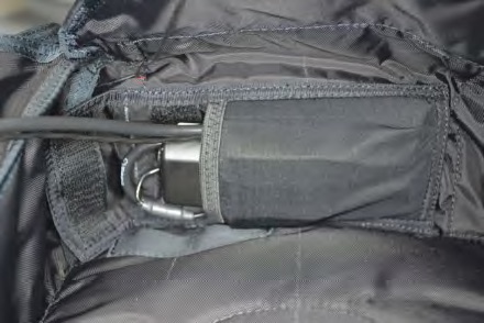
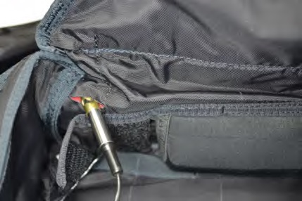
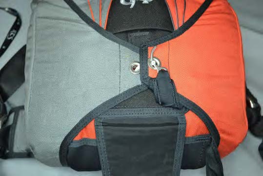
1. Wrap the excess control unit and cutter assembly wiring around the perimeter of the processing unit and place it into the spandex pocket located on the bottom flap of the reserve container.
Note that the wires exiting the processing unit are nearer to one side.
Place this side against the bottom flap.
A small rubber band may be useful in keeping the wires in place on the processing unit.
Note
There are two types of AAD pockets used in Mirage containers. One features openings in the corners of the closing flap that the control unit wire cable and the cutter assembly wire should be passed through, and the other has a strip of velcro for the closing flap that the wires must pass under.
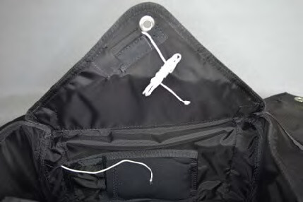
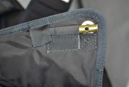
2. Pass the control unit through the opening provided in the reserve pack tray.
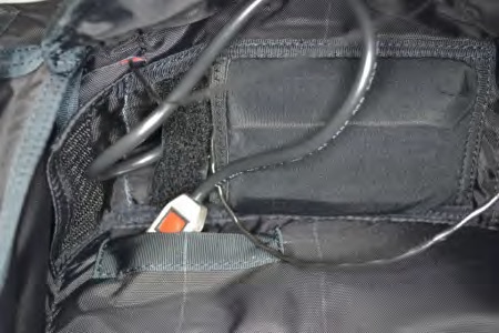
3. Route the control unit and wire cable through the pack tray, exiting at the top right, as shown.
Make sure to leave slack in the wire cable to prevent pulling the control unit out of the spandex pocket when the reserve is packed.
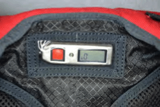
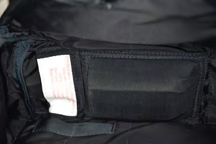
4. Place the control unit into the spandex pocket provided on the back pad.
The display must be visible through the clear vinyl window.
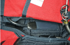
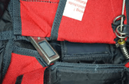
5. Thread a pull-up cord through the elastic AAD cutter keeper and through the reserve bottom flap, exiting the slit provided near the AAD spandex pouch.
“Super-tack” or Cypres loop material works well for this and is provided on new assemblies.
6. Tie the AAD cutter assembly to the pull-up cord and pull it through the No. 3 flap and into the elastic cutter keeper.
Leave enough slack in the wire to prevent strain on the cutter when the reserve is packed.
Remove the pull-up cord.
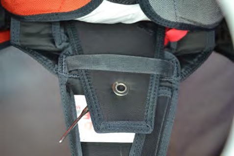
7. Align the hole in the cutter assembly with the grommet of the No. 3 flap.
8. Close the cover on the AAD pocket.
7/03/2024
10 – Installing The Reserve Parachute Canopy
Before installing a reserve canopy in a Mirage, complete the following tasks:
- Check the canopy label to verify that the canopy is manufactured under an FAA TSO C23( ) and is clearly marked.
- Read and understand the Operating Limits section of this manual.
- Determine the operating limits of the entire assembly and record on the packing data card.
- Review any manufacturer Product Service Bulletins and/or FAA Airworthiness Directives that may be in effect for this canopy.
- Thoroughly inspect the canopy and lines for airworthiness.
- Record the required data on the packing data card for the reserve canopy and Mirage harness and container system.
Lay the Mirage out face down with the reserve risers extended fully. The rear risers will be facing up. Make sure that the risers are not twisted.
Attach the reserve parachute canopy to the reserve risers, routing the four line groups to their correct riser. Perform a thorough suspension line continuity check after installation. Use of either Rapide Links or Slinks to attach the reserve parachute canopy suspension lines to the risers is authorized in accordance with the canopy manufacturer’s recommendations.
Follow reserve parachute canopy manufacturer’s instructions for assembling Slinks.
Tacking through the risers to keep the Slinks tabs centered within the riser loops is authorized. Take care not to tack through the Slink line or the tab. Tack in a way that no strain is placed on Slink or its tab during deployment.

When installing Rapide Links, installation of vinyl tubing or fabric slider stops is authorized if recommended by the canopy manufacturer.
Route the left and right reserve parachute canopy steering lines through their corresponding guide rings on the rear reserve risers and attach the toggles to the steering lines in a manner recommended by the canopy manufacturer. Toggles are attached at the point marked on the steering lines by the canopy manufacturer.
Perform a continuity check after installation.
4/28/2016
11 – Installing The Reserve Deployment Bag And Pilot Chute
Substitution of the Mirage reserve deployment bag and/or reserve pilot chute with components made by another manufacturer is prohibited, and voids the TSO.
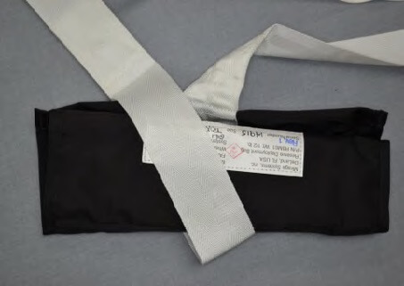
Check the TSO label on the reserve deployment bag to verify that it is the correct size and type for the Mirage reserve container.
Use of a Mirage G3 deployment bag in a Mirage G4 / G4.1 / G4.2 / G4.3 is prohibited.
G4 / G4.1 / G4.2 / G4.3 Reserve Deployment Bag Identification
If there is a dash in the container size (example M5-1/2), use only the numbers on the left side of the dash (M5) to determine the freebag size.
|
Rig Size |
Part Number |
Bag ID |
|
MZS, MXS, MOS |
RBM01-G4.1-MZS, MXS, MOS |
G4 – XOS |
|
MT, MO, MX |
RBM01-G4.1-MT, MO, MX |
G4 – TOX |
|
M1Z, M1, M2 |
RBM01-G4.1-M1, M2 |
G4 – 1,2 |
|
M2S |
RBM01-G4.1-M2S |
G4 – 2S |
|
M3, M4 |
RBM01-G4.1-M3, M4 |
G4 – 3,4 |
|
M3M, M4M |
RBM01-G4.1-M3M, M4M |
G4 – 3,4/M |
|
M3L, M4L |
RBM01-G4.1-M3L, M4L |
G4 – 3,4/L |
|
M5, M6 |
RBM01-G4.1-M5, M6 |
G4 – 5,6 |
|
M7, M8 |
RBM01-G4.1-M7, M8 |
G4 – 7,8 |
Thoroughly inspect the reserve deployment bag and pilot chute for airworthiness.
Verify that the correct size safety stow is installed from the chart below.
Deployment Bag Safety Stow Finished Lengths And Identification Codes
|
Safety Stow Size |
Finished Length |
Thread Color Identification Code |
Fits G4.1 Reserve Deployment Bag Sizes |
|
SMALL |
5-3/4″ |
YELLOW |
G4-XOS / G4-TOX |
|
MEDIUM |
6-1/2″ |
BLACK |
G4-1,2 / G4-2S / G4-3,4 / G4-3,4M / G4-3,4L / G4-5,6 |
|
LARGE |
7-1/4″ |
RED |
G4-7,8 |
Replacement safety stows are available from Mirage Systems, Inc.
Attach The Reserve Pilot Chute To The Reserve Deployment Bag
If an AAD is to be installed on a Mirage built after 2004, the use of a Mirage reserve pilot chute with a concave top is mandatory.
Older flat top Mirage pilot chutes are authorized on earlier Mirages but the modern concave top is recommended.
Attach the reserve pilot chute to the reserve deployment bag by passing the looped end of the bridle through the two bridle loops on the reserve pilot chute.
Then pass the deployment bag through the looped end of the bridle, forming a larks head knot.
Center the larks head knot on the pilot chute bridle loops and cinch tight.
Securing the larks head knot in place by hand tacking with safety tie thread is authorized, but not required.
2/18/2020
12 – Installing A Reserve Closing Loop
Mirage reserve containers are shipped with Cypres ® reserve closing loops installed.
If a different brand of AAD is installed, remove and replace the Cypres® closing loop with one recommended by that AAD manufacturer.
Note
The Cypres® loop and disc system, (with or without silicon treatment) is not to be used in combination with other AADs. See Cypres® Safety and Rigging Notice 20110421, April 21, 2011.
Closing Loop Length
The correct closing loop length needed is always a balance between the proper compression of the reserve pilot chute and the ability to pull the ripcord. The loop needs to be short enough to compress the pilot chute so that the spring can’t tilt or move inside the packed reserve, but yet long enough that the pull force required to move the ripcord pin remains under the 22 lb. maximum, as required by NAS 804.
The actual closing loop length required is affected by several factors, such as the size of the reserve canopy and the size of the Mirage reserve container, the experience of the rigger packing the Mirage, distribution of the canopy bulk within the reserve deployment bag, and even the climate where the reserve is being packed. A longer closing loop may be required if packing a reserve in a desert location, if the last repack was done in a humid location.
Before installing a rigger seal, we recommend that a ripcord pull-force test be done to verify that the ripcord pin can be moved with less than 22 lbs. of force.
Follow instructions from AAD manufacturer to secure the disc on the closing loop, and to determine the proper size for the loop opening.
Closing loop lengths vary for a variety of reasons that can include humidity, size of the canopy, and rigger experience. Average closing length is between 4.0″ to 5.0″
Use the suggested starting lengths from the list below and adjust as needed. Measurements are from the end of the closing loop to the disc.
If packed correctly (not over stuffed or too long of a loop) the reserve pin cover tongue will be fully inserted and laying flat, not bent.
|
Canopy Size |
Starting Loop Length (Adjust as needed) |
|
|
PDR-99 /OP-106 |
4.0” |
|
|
PDR-106/OP-113 |
4.0” |
|
|
PDR-113/OP-126 |
4.0” |
|
|
PDR-126/OP-143 |
G4.1 : 4.50” / G4.2 : 4.25” |
|
|
PDR -143/OP-160 |
G4.1 : 4.50” / G4.2 : 4.25” |
|
|
PDR-160/OP-176 |
G4.1 : 4.75” / G4.2 : 4.25” |
|
|
PDR-176/OP-193 |
G4.1 : 4.75” / G4.2 : 4.25” |
|
|
PDR-193/OP-218 |
G4.1 : 5.0” / G4.2 : 4.5” |
|
|
PDR-218/OP-235 |
G4.1 : 5.0” / G4.2 : 4.5” |
|
|
PDR-235/OP-253 |
G4.1 : 5.25” / G4.2 : 5” |
|
|
PDR-253
|
G4.1 : 5.25” / G4.2 : 5” |
Helpful Hint
The proper closing loop length can be verified before the reserve container is closed.
- Install a closing loop and thread the long pull-up cord through it. After placing the packed bag in the reserve container and V-folding the bridle, thread the long pull-up cord through the No. 1 flap grommet.
- Push down on the No. 1 flap and the packed bag with one hand, and pull up with maximum effort on the long pull-up cord with the other. If the closing loop is the correct length, you should be able to pull 3/4” to 1” of the loop past the No. 1 flap.
- At this point if a length adjustment is needed, fold the No. 1 flap back and reach under the packed bag inside the reserve container to pull the closing loop disc and knot from under the retaining elastic and out the top of the reserve container. This can be done without disturbing the risers or packed parachute.
- Make the length adjustment needed, then use the still attached pull-up cord to return the closing loop to the reserve container. Make sure the disc is reseated on the grommet under the retaining elastic. Recheck the closing loop length in the same manner.
2/21/2018
13 – Installing A Reserve Static Line (RSL)
“No Velcro” RSLs are used on all Mirage models manufactured after January 2008.
Previous RSLs used velcro to attach the RSL to the left rear reserve riser.
A Mirage RSL Is Optional
The RSL on your Mirage G3, G4.1, or RTS is an optional accessory. All models are approved for use with the RSL installed, installed but not engaged, or not installed at all. Use of the RSL may not be desirable under all circumstances. If you are not sure if an RSL is right for you, get advice from a qualified instructor.
WARNING!
An RSL should not be relied upon to activate your reserve! Always pull your reserve ripcord when the main parachute is released, even if you think the RSL is engaged!
The RSL WILL NOT open the reserve parachute if DISENGAGED from the main riser. It also MAY NOT FUNCTION AS INTENDED IF IMPROPERLY INSTALLED OR DAMAGED. Your rigger should inspect it periodically for proper installation, wear, or damage.
Caution
Only RSLs made by Mirage Systems, Inc., are authorized for use on Mirage harness and container systems.
How It Works
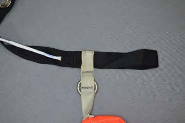
The RSL is a simple, passive system consisting of a short lanyard (static line) connecting the left main parachute riser to the reserve ripcord. When the main parachute is released, the RSL pulls the reserve ripcord shortly after the left riser leaves the harness ring.
A quick release shackle on the RSL allows the main parachute to be released without opening the reserve parachute. This feature is useful in certain situations, such as landing in high winds, breaking away from an entanglement with another parachutist, or for main parachute maintenance. Questions about how to use an RSL can be answered by a qualified instructor.
Mirage RSLs are made in three lengths, 23”, 24”, and 25”.
- If your Mirage has a 25” or 26” ripcord, the correct RSL is 23” ; if it has a 27” or 28” ripcord, the correct RSL is 24”; and if it has a 29” or 30” ripcord, the correct RSL is 25” .
- Contact Mirage Systems, Inc. to determine the correct length ripcord to use if you have lost yours. You will need to provide the serial number of the rig.
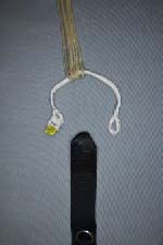
The RSL consists of a short webbing lanyard with a quick release shackle at one end, and a small ring at the other. While a very small Velcro patch is needed to retain slack, none is exposed that could damage the rig.
Installation of the RSL
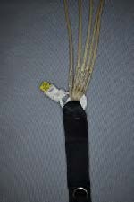
To begin installation of the Mirage RSL, fold and press the Velcro patches together that are near the release shackle.
With the quick release shackle down, insert folded RSL into ripcord housing channel.
The hook portion of the quick release shackle should be facing outboard, and the tab should be facing inboard.
Loosely route the remaining RSL toward the reserve container.
Remove any twists and place it under the flap on the RSL retainer.
Close the RSL retainer.
Remove any excess slack between the cover and the ripcord channel, but don’t pull it too tight.
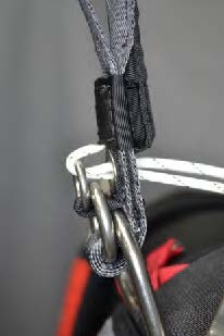
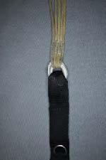
Route the RSL directly to the guide rings on the reserve pin flap.
Be sure to remove any twists.
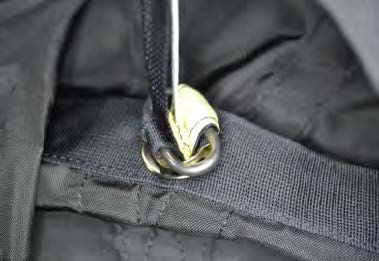
The ripcord cable must pass through the first guide ring, the RSL lanyard ring, and the second guide ring, after exiting the ripcord housing.
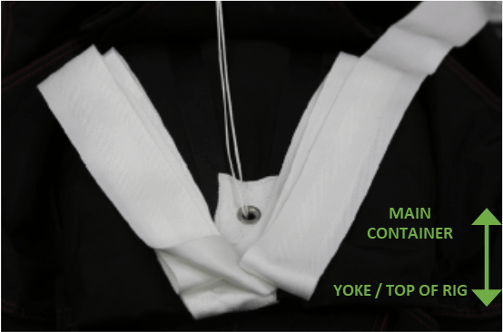
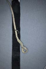
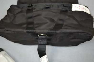
Neatly stow excess RSL lanyard between the yoke and the top of the reserve container.
Don’t pull tight.
Model G4.1 ONLY
Pass the ripcord pin flap through the retaining loop on the protector flap AFTER the RSL has been assembled.
When the reserve is packed, almost no RSL should be visible on the outside of the container.
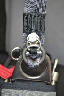
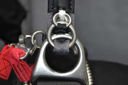
Attach the quick release shackle to the ring provided on the riser.
Mirage RSLs were designed and tested to be used with risers made by Mirage only.
The attachment ring location MUST BE BELOW the riser grommet.
Risers made by another manufacturer may not have the attachment ring in the required location.
Always have a qualified rigger inspect your risers to determine if they are compatible with the Mirage RSL.
4/28/2016
14 – Packing The Reserve Parachute
Riggers are to use standard rigging practices, techniques and tools in packing a Mirage reserve container. No special tools are required, other than a long pull-up cord, 60” (+/-) long. Refer to the information provided in this manual as a guide. If you have any questions, contact Mirage Systems, Inc.
Note
The use of a ratcheting closing tool is discouraged. Ratcheting closing tools can exert excessive force which can weaken or break the reserve container closing loop, damage reserve flap grommets, and possibly damage the AAD cutter. If you do use a ratcheting closing tool, do so carefully.
Lay the Mirage and reserve parachute canopy out for packing, face down and head toward the canopy.
When the canopy inspection and line continuity check are completed, fold the canopy according to the canopy manufacturer’s instructions. The PRO packing method, or a BASE canopy type PRO packing method, is recommended.
When folding is complete, ensure that all suspension and steering lines are in the center of the folded canopy on top of the center cell, and that half of the canopy is folded to the right of the lines, and half of the canopy is folded to the left of the lines.
Long fold the canopy slightly wider than the closing flap of the reserve deployment bag and stow the slider as recommended by the canopy manufacturer.
Fold the slider and grommets back making an S-fold 3” to 6” top to bottom. The slider grommets should now be located at the bottom edge of the folded canopy.
The second S-fold brings the canopy stack down over the first S-fold even and even with the bottom edge.
The length of the second S-fold will depend upon the available space between the bottom of the deployment bag and the closing loop grommet in the bag, but should be about 4” to 6” overall.
This second fold should begin to create the desired wedge shape of the reserve container. The majority of the canopy bulk should now be at the bottom of the stack. This will end up in the bottom of the reserve bag, between the opening and the closing loop grommet.

For the next step, it may be helpful to have your knees against the bottom edge of the stacked canopy.
Spread the two sides of the remaining folded canopy apart slightly and locate the center seam. Follow the center seam toward the center cell intake, clearing the seam as you go, until the center cell intake is located. Fold the intakes left and right away from the center seam and gently roll the center seam down toward the floor, forming the folded canopy into a molar shape.
Unlike the G3, the G4 requires somewhat thicker molar ears in order to fill the top of the reserve container. Fold the molar ears under 5” to 8” .
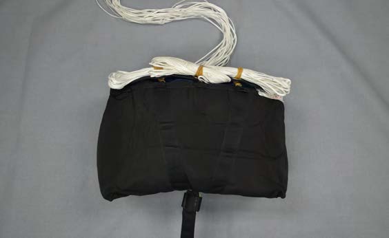
Slide the deployment bag under the folded canopy and place your knees on the edge of the bag closing flap. Open the bag with one hand and with the other hand, slide one side of the folded canopy into the bag. Repeat for the other side.
IMPORTANT – Fill the top of the bag as full as possible.

Close the bag opening by making two locking stows, left or right,with the suspension lines.
Micro-line stows should be 2” long (+/-), and Dacron line stows should be 3” long (+/-).
When the locking stows are completed, ensure that the zig-zag stitching on the safety stow is centered in the retention channel.
CAUTION!
Prior to stowing the suspension lines, always cover the hook velcro located inside the reserve deployment bag line stow pocket by attaching temporary pile velcro strips. Hook velcro can cause damage to the reserve canopy suspension lines. Remove temporary velcro after suspension lines are stowed.
Stand the bag on the floor with the closing flap up. S-fold the remainder of the suspension lines in the line stow pocket, starting in the bottom corners, left or right. Continue left or right until 4” (+/-) of the suspension lines remain outside the pocket. To reduce line bulk, evenly distribute the lines within the pocket.
Remove the temporary pile velcro and mate the velcro strips on the line stow pocket, making sure that no suspension lines are trapped between the two velcro halves.
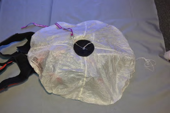
While the bag is still standing with the closing flap up, use your hand to compress the packed canopy at the center of the closing flap. This will make a space for the AAD when the bag is placed in the reserve container.
Install a 60” (+/-) long pull-up cord through the reserve container closing loop.
Lift the packed bag toward the reserve container and place the risers into the reserve container. Make sure not to twist or rotate the bag. Spread out the four risers side-by-side across the bottom of the reserve container. Neatly organize the 4” to 6” of slack suspension lines between the bag and risers.
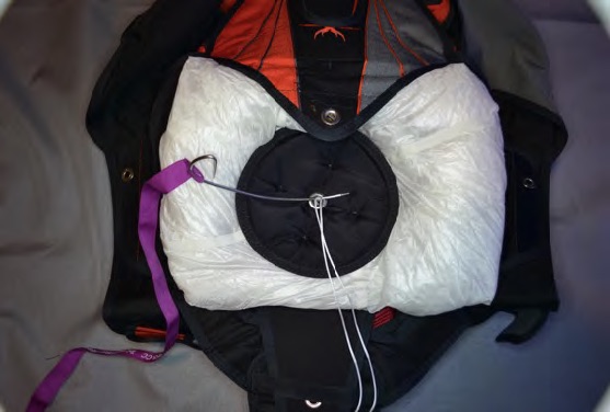
Lay the reserve bag in the container and thread the pull-up cord through the grommet in the bag.
Place your knee on the center of the bag to keep it in place while you push the bag into the corners of the reserve container, filling the corners.
With both hands, press inward on the bottom center of the bag to make room for the AAD while pushing the bag downward into the corners of the reserve container.
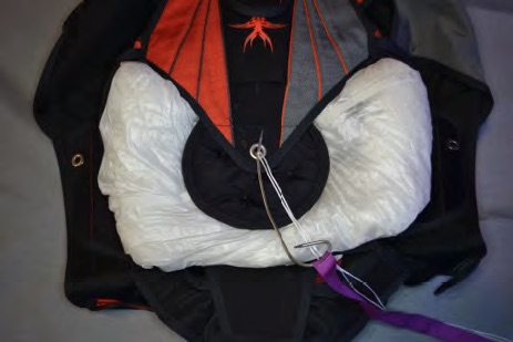
Starting at the bridle attachment point on the bag, V-fold the bridle as shown, removing any twists in the bridle.
Fold all but 3’ to 4’ of the bridle in this manner.
Bridle folds should be evenly distributed to the left and right of the closing loop grommet.
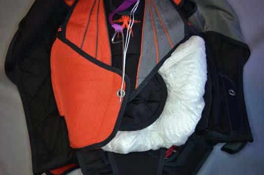
Thread the long pull-up cord through the grommet in the No. 1 flap and close the flap over the folded bridle.
Make sure the folded bridle is kept away from the grommets.
The remaining 3’ to 4’ of bridle should exit from under the bottom edge of the No. 1 flap, left or right of the grommet.
Helpful Hint
At this point, the proper closing loop length can be verified before the reserve container is closed.
- Push down on the No. 1 flap and the packed bag with one hand, and pull up with maximum effort on the long pull-up cord with the other. If the closing loop is the correct length, you should be able to pull 3/4” to 1” of the loop past the No. 1 flap.
- If a length adjustment is needed, fold the No. 1 flap back and reach under the packed bag inside the reserve container to pull the closing loop disc and knot from under the retaining elastic and out the top of the reserve container. This can be done without disturbing the risers or packed parachute.
- Make the length adjustment needed, then use the still attached pull-up cord to return the closing loop to the reserve container. Make sure the disc is reseated on the grommet under the retaining elastic. Recheck the closing loop length in the same manner.
- Pin the closing loop through the No. 1 flap with a temporary packing pin.
Helpful Hint
Place your knee or foot on the center of the No. 1 flap and apply pressure while pulling up on the No. 4 and No. 5 reserve container side flaps. Work the canopy into the corners of the container and away from the closing loop.
This is important for bulk distribution and proper pilot chute seating.
Fold the remaining bridle across the No. 1 flap:
Without the Trap System – Distribute the bulk evenly
With the Trap System – Distribute the bulk more to the non-Trap side.
Helpful Hint
A long wire bodkin or rifle cleaning rod is helpful for the next step.
Thread the long pull-up cord through the reserve pilot chute base and out through the grommet in the top of the pilot chute.
If an AAD is to be installed on a Mirage built after 2004, the use of a Mirage reserve pilot chute with a concave top is mandatory.
Older flat top Mirage pilot chutes are authorized on earlier Mirages but the modern concave top is recommended.
CAUTION!
Make sure that the pull-up cord passes through the center of the pilot chute spring and does not pass around or through any part of the spring, the bridle, or the netting.
Center the base of the pilot chute spring over the grommet in the No. 1 flap while folding the bridle away from the grommet. Make sure that none of the bridle is near the closing loop.
Compress the pilot chute spring. Due to the strength of the pilot chute spring, it is best to collapse the spring coils by starting at the bottom and pushing a single coil down, alternating left or right, until all are completely collapsed.
DO NOT wrap any part of the pilot chute canopy or mesh around the spring!
Helpful Hint
A packing paddle or leverage tool attached to the pull-up cord is required for the next step.
While pushing down on the pilot chute to keep it compressed, remove the temporary packing pin from the No. 1 flap, pull the closing loop through the grommet in the top of the pilot chute, and reinsert the temporary packing pin in the closing loop above the pilot chute. Note that the top of the reserve pilot chute is numbered 2.
If the closing loop is the correct length, the coils of the pilot chute spring should not wobble excessively when the pilot chute is compressed.
Gently pull on the pilot chute canopy to spread it and the mesh to their full diameter.
IMPORTANT – Make sure that all canopy fabric and mesh are withdrawn from within the coils of the pilot chute spring.
Place your knee or foot on the center of the pilot chute top and apply pressure while pulling up on the No. 4 and No. 5 reserve container side flaps. Work the pilot chute into the packed bag, and work the canopy into the corners of the container.
Filling the corners completely is very important for bulk distribution and proper pilot chute seating.
Accordion fold the pilot chute canopy under from the top and under from the bottom until the parallel edges of both folds are approximately 1-1/2” to 2” from the edge of the pilot chute top.
CAUTION!
DO NOT place any portion of the folded canopy and mesh under or in the spring.
DO NOT place any portion of the folded canopy and mesh around or under the bag.
IMPORTANT – The pilot chute canopy and mesh should always remain on top of the bag and NOT BE wrapped alongside, around or under it in such a way as to hinder its launch.
Thread the pull-up cord through the hole in the AAD cutter assembly (if installed), then through the grommet on the No. 3 flap.
IMPORTANT!
Double check to make sure the pull-up cord passes through the hole in the AAD cutter assembly (if installed).
Wrap the ends of the folded pilot chute around the pilot chute top and place them under the No. 3 flap with the ends facing the bottom of the container. Again, make sure that none of the canopy or mesh is placed under or in the pilot chute spring. Also, make sure that none of the canopy or mesh is tucked or wrapped around or under the bag; no canopy or mesh should be between the bag and the sides of the container.
CAUTION!
If an AAD is installed, avoid using excessive force on top of the reserve pilot chute when closing the No. 3, 4, 5, and 6 flaps.
Do not use a closing plate smaller than the diameter of the pilot chute cap on top of these flaps.
Damage to the AAD cutter could result!
Using a packing paddle or leverage tool attached to the pull-up cord, draw the grommet in the No. 3 flap to the grommet in the pilot chute by pulling toward the top of the reserve container.
Don’t remove the temporary packing pin until the two grommets are touching.
Pull the closing loop through the grommet in the No. 3 flap and reinsert the temporary packing pin in the closing loop above the No. 3 flap.
Once the No. 3 flap is pinned, check the coils of the pilot chute to make sure that they are aligned and centered under the No. 3 flap grommet.
Thread the pull-up cord through the grommets in both the No. 4 and No. 5 flaps.
Using a packing paddle or leverage tool attached to the pull-up cord, draw both grommets toward the center.
Do not remove the temporary packing pin above the No. 3 flap.
While drawing the No. 4 and No. 5 flaps together, firmly slap the side walls of the reserve container to expel air and nudge the flaps closer together.
IMPORTANT!
Do not force either of the side flaps to the center. Work gradually to prevent damage to the reserve container.
Drawing both flaps to the center at the same time will help keep the reserve container symmetrical.
Once the flaps have been drawn to the center over the closing loop, withdraw the pull-up cord from the No. 5 flap, while keeping tension on the pull-up cord through the No. 4 flap.
Remove the temporary packing pin from the No. 3 flap.
Using a packing paddle or leverage tool attached to the pull-up cord, draw the closing loop through the No. 4 flap grommet and reinsert the temporary packing pin in the closing loop above the No. 4 grommet.
Thread the pull-up cord through the grommet in the No. 5 flap.
Using a packing paddle or leverage tool attached to the pull-up cord, draw the closing loop through the No. 5 flap grommet and reinsert the temporary packing pin in the closing loop above the flap.
Note
At this point it should require maximum effort to draw no more than 1/4” of the closing loop beyond the No. 5 flap.
If installed, make sure that the reserve ripcord passes through the first RSL guide ring on the No. 6 flap, then through the RSL ring, then through the second guide ring.
Insert the No. 6 flap and ripcord pin through the retaining loop on the reserve pin cover flap.
Thread the pull-up cord through the grommet in the No. 6 flap.
Using a packing paddle or leverage tool attached to the pull-up cord, draw the closing loop through the No. 6 flap grommet and insert the ripcord pin in the closing loop above the flap.
IMPORTANT!
Measure the force required to move the ripcord pin to verify that it takes less than the required maximum of 22 lbs.
Inspect and account for all tools used.
Seal the ripcord pin with 5 lb. seal thread in accordance with The Parachute Manual and complete the packing data card.
Close the reserve pin cover.
9/18/2025
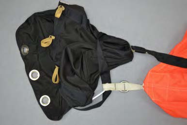
15 -Trap System Packing Instructions

The Mirage TRAP SYSTEM™ is a unique approach to how a Main Assisted Reserve Deployment (MARD) system functions. The Trap System design is simple, reliable, and rigger friendly.
The TRAP SYSTEM™ is not attached to the reserve bridle in any way until needed. Only when the main parachute is cutaway does the Trap engage and aid in deployment of the reserve parachute. If the ripcord is pulled, or an AAD deploys the reserve, there is no mechanical device that must first detach to allow your reserve to deploy normally.
The TRAP SYSTEM™ includes these parts:
- The Trap and the Trap Door (cover), which are sewn to the No. 1 pilot chute kicker flap of the Mirage reserve container;
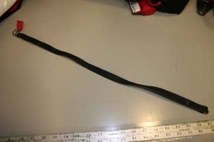
- A red RSL lanyard with a Trap Line installed;
- A modified reserve bridle which is simply folded and sewn for insertion into the elastic keeper;
- A pair of Mirage Systems, Inc. main risers with a factory installed RSL ring.
Caution
Use ONLY main risers made by Mirage Systems, Inc., with a factory installed RSL ring!
The TRAP SYSTEM™ has not been tested using risers built by other manufacturers.
Use ONLY genuine TRAP SYSTEM™ parts available from Mirage Systems, Inc.
The use of locally modified reserve freebag bridles or locally made replacement RSL lanyards and Trap Lines is not authorized!
The following instructions should be followed closely to properly assemble and pack the TRAP SYSTEM™.
If you have questions, contact Mirage Systems, Inc.
Assembly
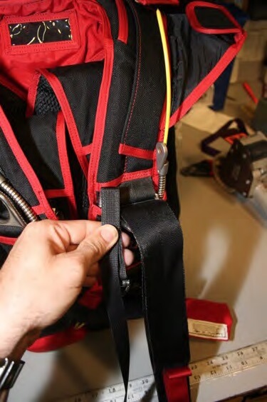
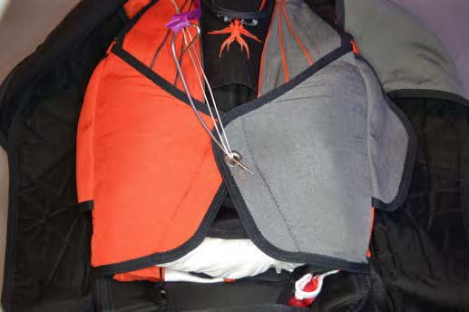
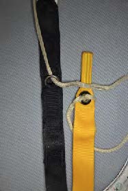
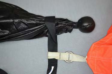
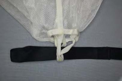
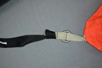
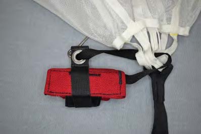
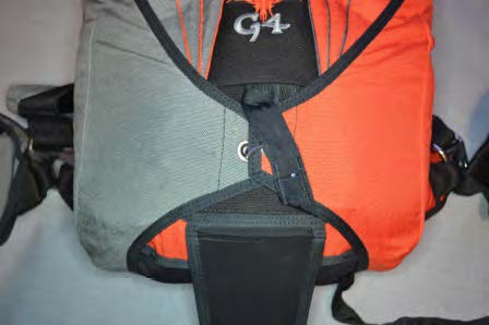
1. Fold the RSL together, mating the velcro strips, and insert under yoke with snap shackle tab facing inward.
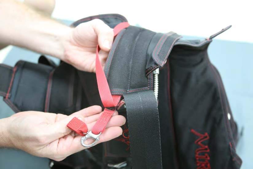
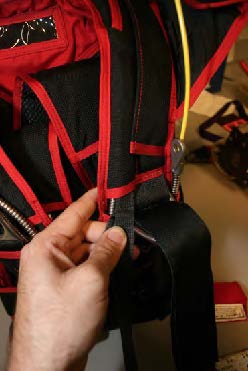
2. Route the RSL over the yoke toward the reserve container and place under the lip of the RSL retainer (a half-twist outward is helpful).
WARNING
DO NOT ROUTE THE TRAP RSL OR TRAP LINE AROUND OR THROUGH THE RESERVE RISERS. THE RISERS MUST BE ABLE TO FULLY EXTEND FOR PACKING WITHOUT DISTURBING THE TRAP RSL.
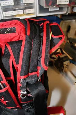
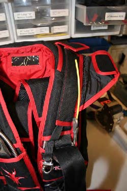
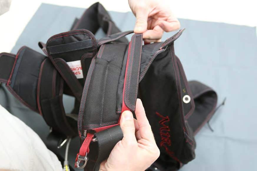
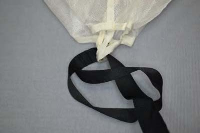
3. Fold the retainer and RSL onto the yoke, removing any twist in the RSL.
The label on the RSL should now be facing up.
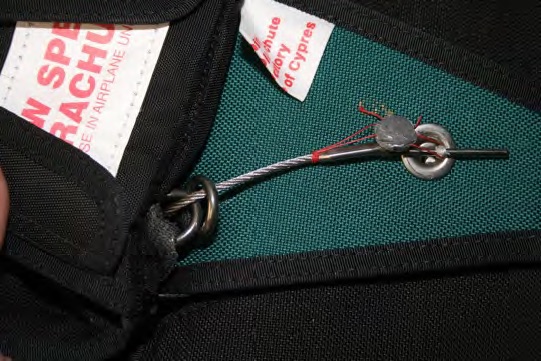
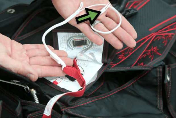
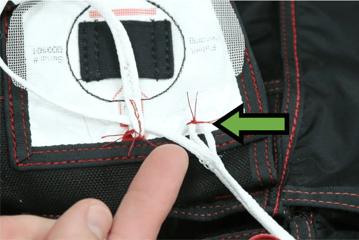
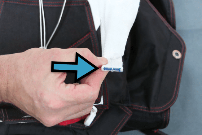
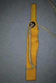
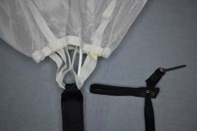
4. Pull the Trap Line through the loop on the end, forming a cinch. The end loop has red stitching.
Helpful Hint
A clamp may be used to keep the Trap Door folded out of the way during the next steps.
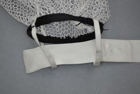
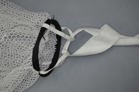
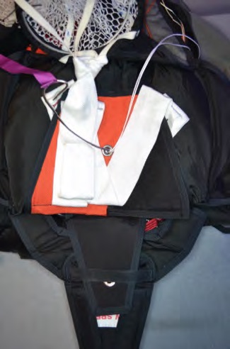
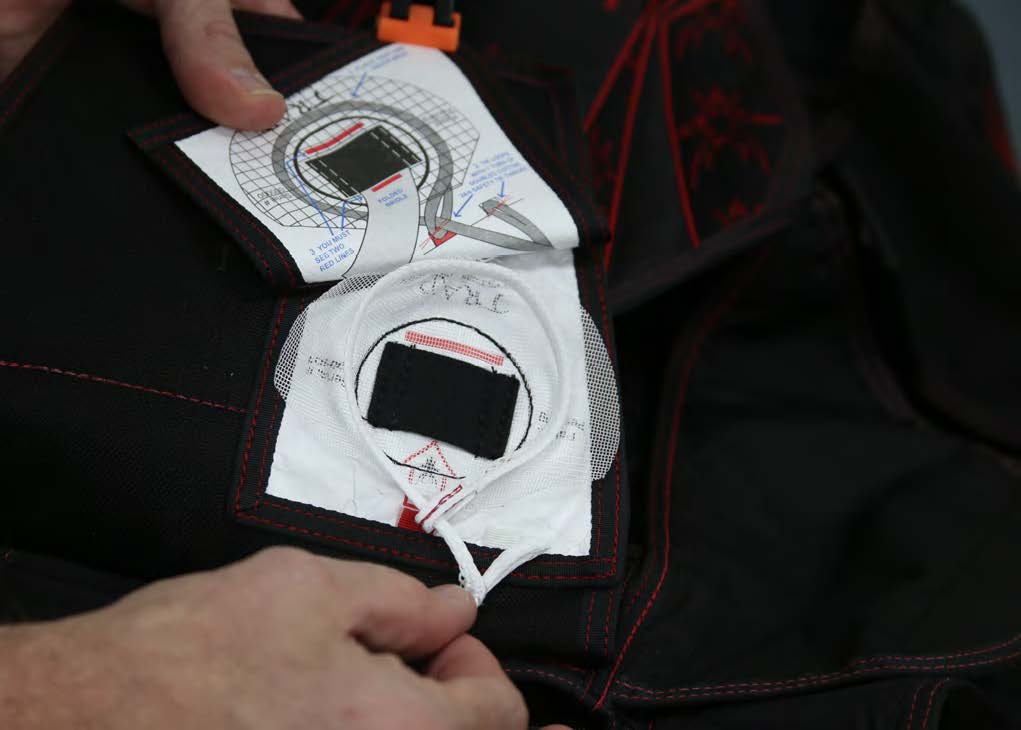
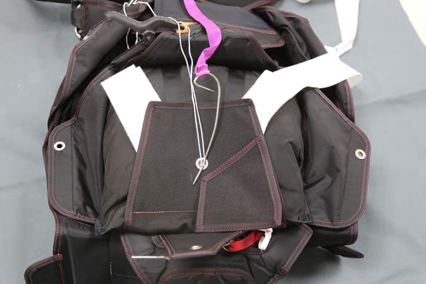
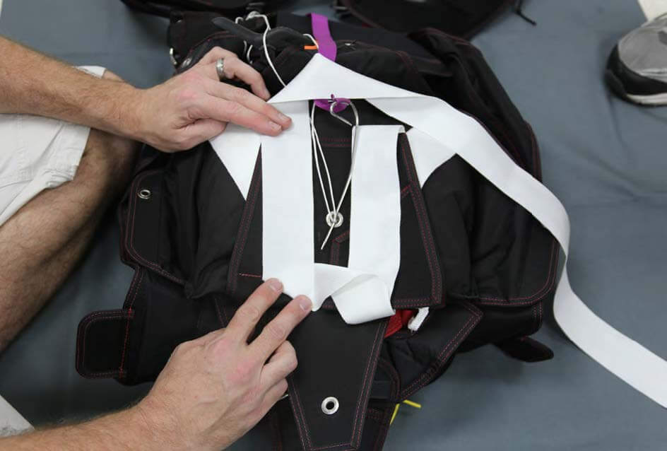
5. Place the Trap Line on top of the mesh as illustrated on the inside of the Trap Door.
6. Thread a doubled length of cotton 24/4 safety tie thread through the end loop on the Trap Line, and the red tab on the Trap.
Do not use a needle to pierce the end loop or Trap Line.
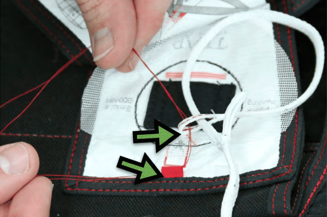
7. Tie the end loop and red tab together with a surgeon’s knot and a square knot.
Cut thread leaving 1/4”– 1/2” (.635cm – 1.27cm) tails.
Make sure that Trap Line is free to slide through the loop after the knot is tied.
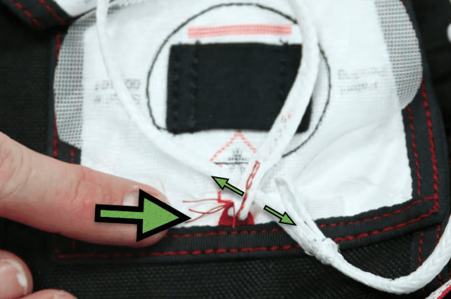
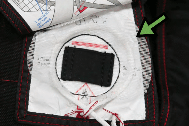
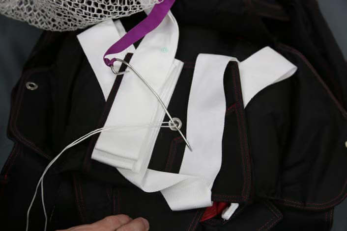
8. Tie the white loop on the Trap Line and the white tab on the Trap together using doubled cotton 24/4 thread.
Cut thread leaving 1/4” – 1/2” (.635cm – 1.27cm) tails.
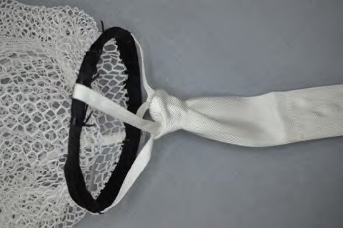
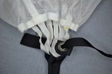
9. IMPORTANT.
Place the Trap Line UNDER the mesh, as shown. The loop should be evenly distributed.
Smooth the mesh.
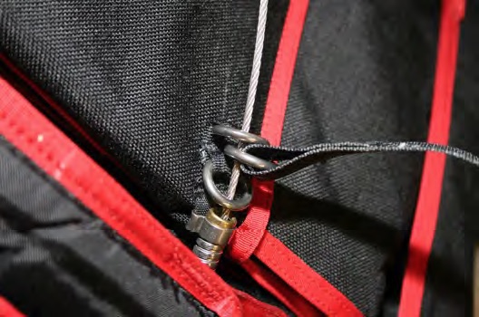
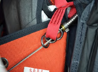
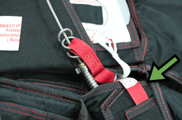
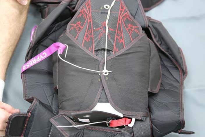
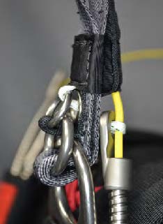
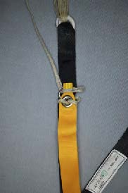
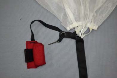
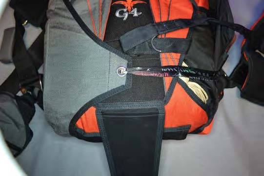
10. With the loop for Trap Line on the RSL facing up, route the ripcord cable through first guide ring on No. 6 reserve pin flap, the ring on the RSL, then the second guide ring on the No. 6 reserve pin flap, as shown.
Make sure that the RSL and Trap Line are not twisted.
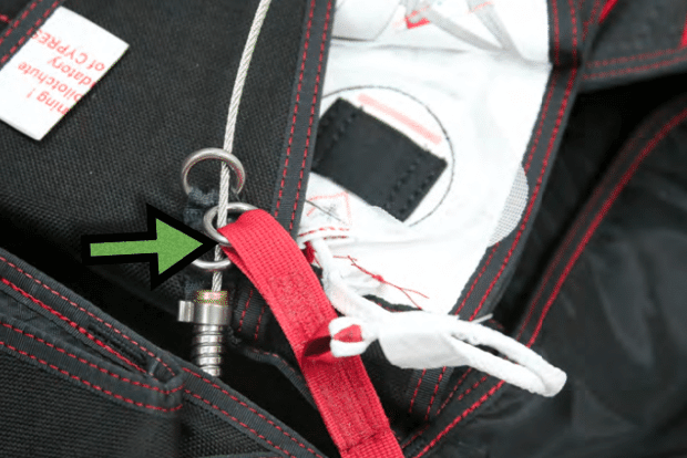
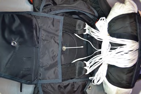
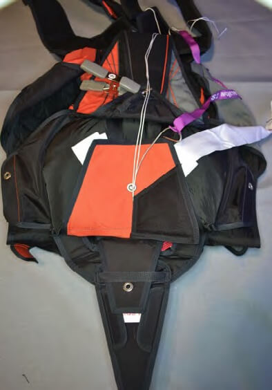
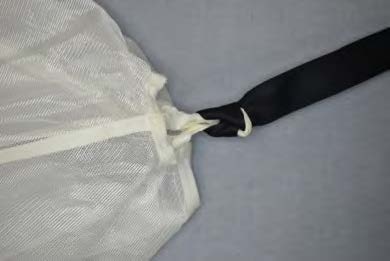
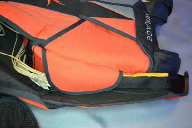
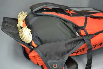
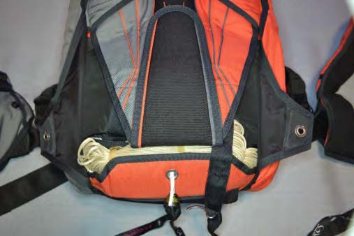
11. Neatly tuck excess RSL and Trap Line between the reserve container and the back pad, as shown. Remove the clamp (if used).
Packing
12. Fold the reserve canopy in accordance with the canopy manufacturer’s instructions and place in the reserve bag in the normal manner.
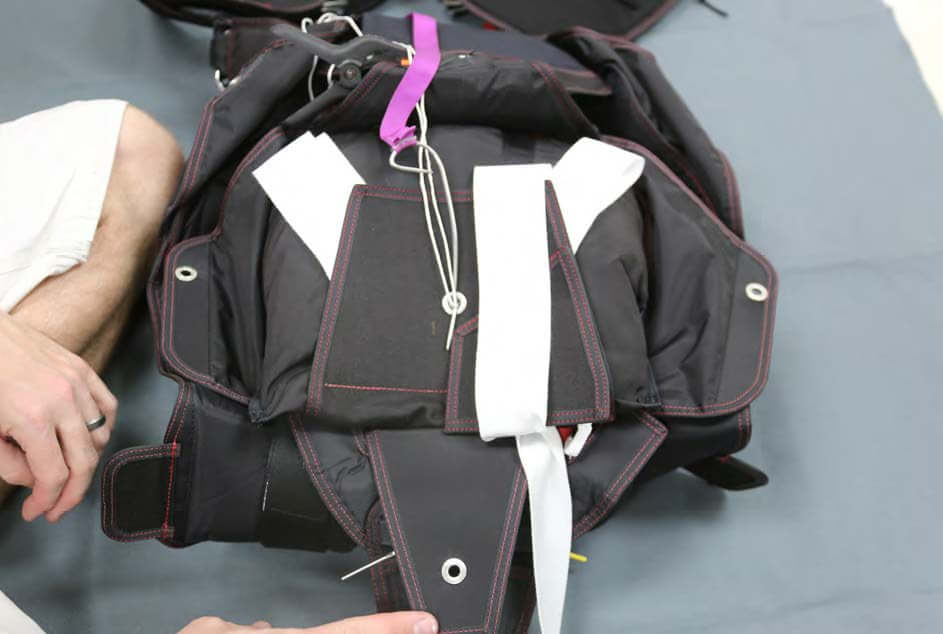
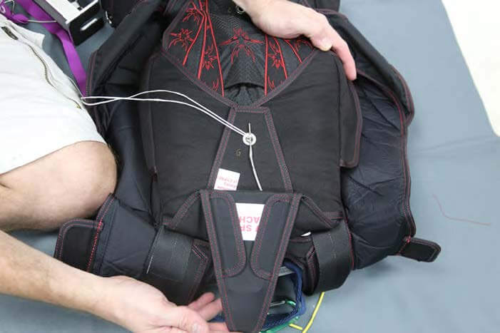
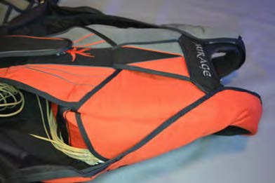
13. Place the packed reserve bag into the reserve container. The excess Trap Line and RSL should be inboard of the stowed reserve riser.
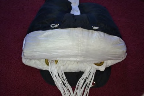
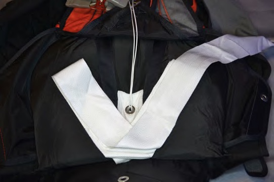
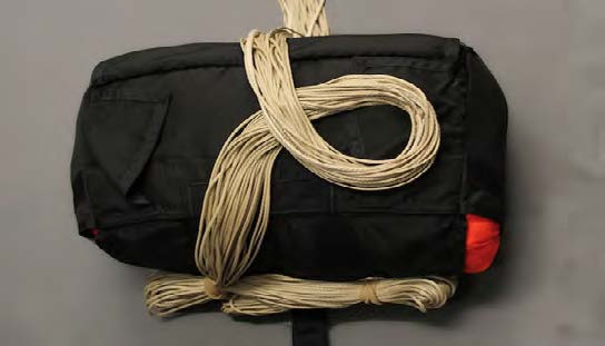
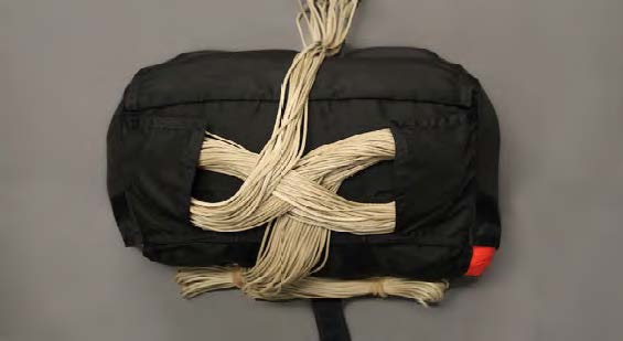
14. Starting on rigger’s left, make two stows of the reserve bridle, then make 1-1/2 stows on the right, forming a “V”, on top of the packed bag.
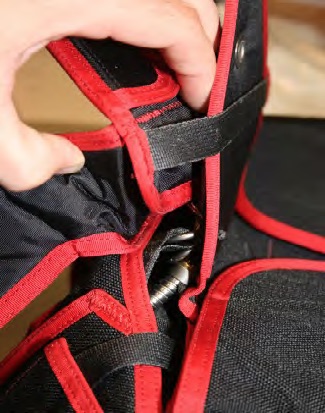
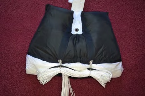
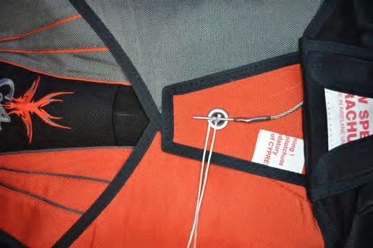
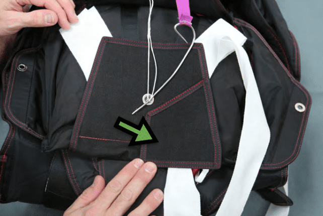
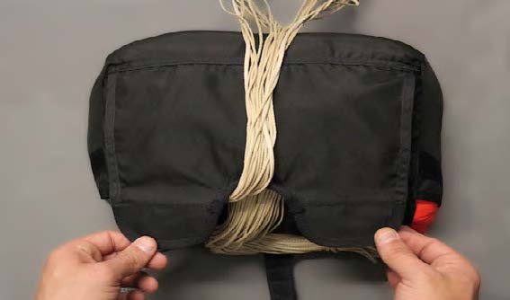
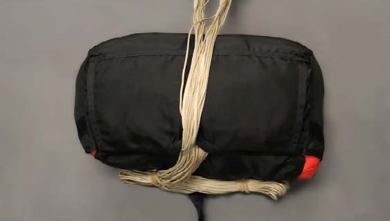
15. Close the No. 1 kicker flap over the stowed bridle with the bridle exiting at the rigger’s upper right and pin in place.
16. Fold the bridle over the No. 1 kicker flap toward the top of the reserve container, removing any twists.
Fold the bridle together on the BLUE line.
The RED line should now be facing DOWN toward the kicker flap.
17. Rotate the folded end of bridle under toward the bottom of the reserve container.
The RED line is now facing UP and the remainder of the bridle running to the reserve pilot chute should be DOWN.
There should be no twists in the bridle.
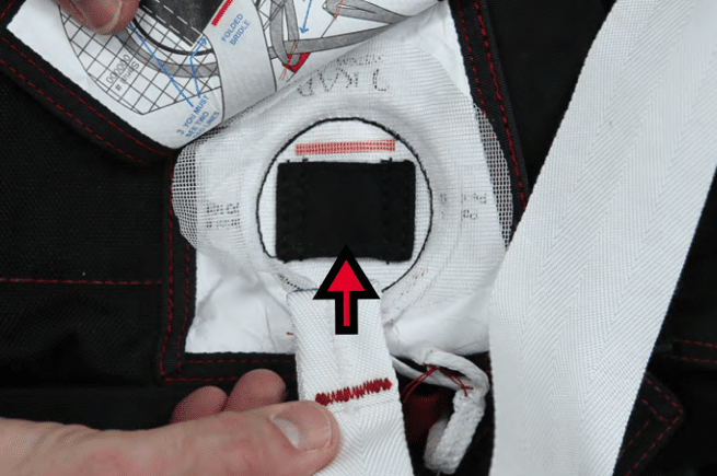
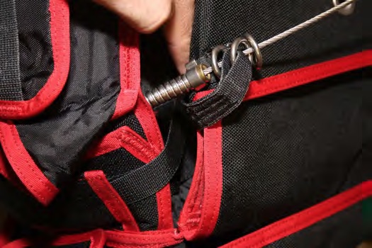
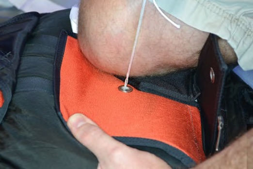
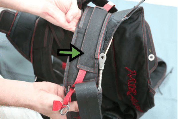
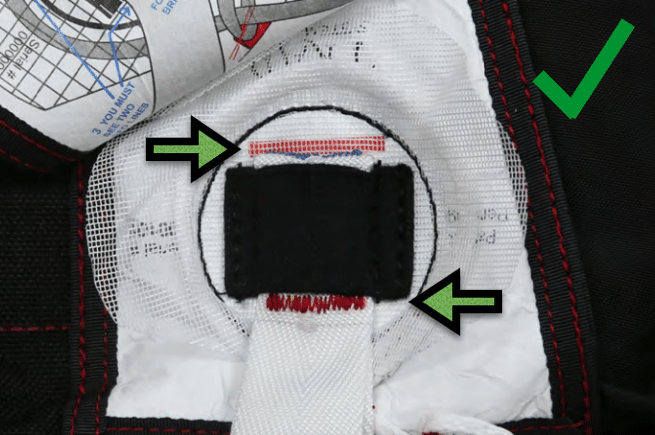
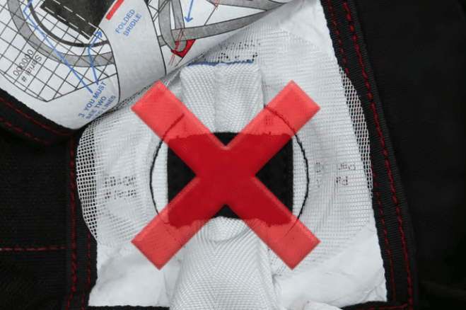
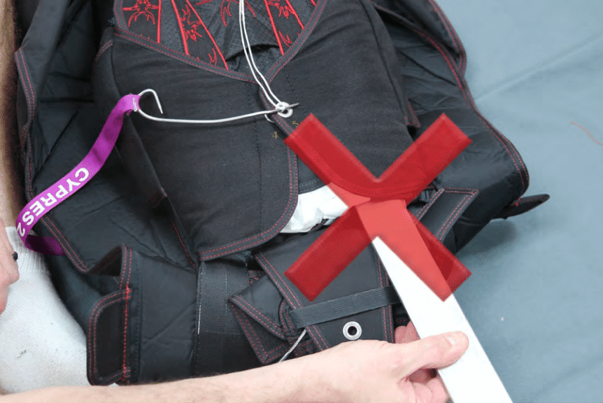
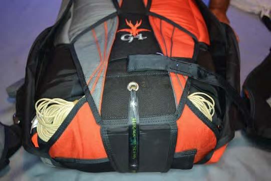
18. CAUTION: Insert the folded bridle under the elastic keeper in the DIRECTION OF THE RED ARROW printed on the Trap label.
19. The bridle should only extend beyond the elastic enough to slightly see the blue line.
When properly stowed TWO RED LINES MUST BE VISIBLE!
Helpful Hint
The folded bridle may be pushed through the elastic loop and then pulled back until the blue line is even with the edge of the elastic.
CAUTION: DO NOT pack the TRAP SYSTEM™ with the bridle EXTENDED beyond the RED line printed under the mesh.
20. Remove the clamp (if used). Close the Trap Door.
21. Place the bridle loosely on top of the Trap Door, using caution not to pull the bridle out of the elastic keeper.
Tuck excess bridle under the edge of the No. 1 kicker flap.
22. Make a short “W” fold placing the remainder of the bridle on the opposite side of grommet.
Do not twist.
23. Stow the remainder of the bridle on the rigger’s left.
24. Compress the pilot chute and close the reserve container 3, 4, and 5 flaps in the normal manner.
25. On the G4.1, place the No.6 ripcord pin flap and ripcord through the retainer on the ripcord pin cover flap BEFORE pulling the closing loop through the No. 6 flap.
CAUTION:
Do not use a packing paddle near the Trap.
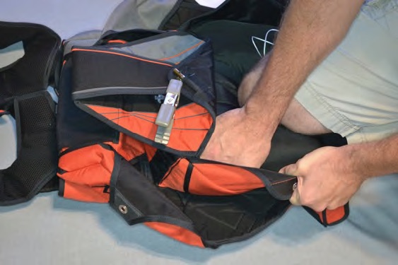
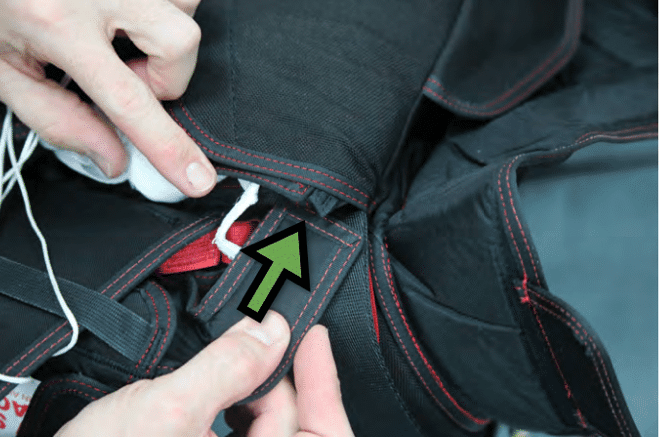
26. Insert the reserve container tuck tabs between the reserve risers and the reserve freebag.
Make sure that the Trap Line and/or RSL are not disturbed when inserting the tuck tab.
The Trap Line and RSL must be inboard of the tuck tab.
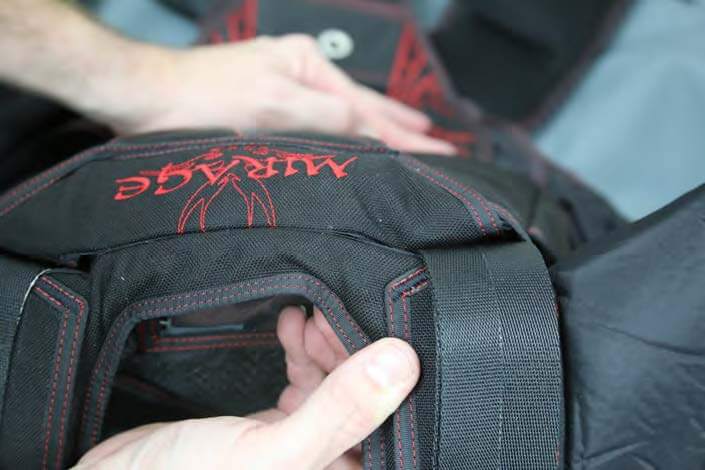
27. Close the No. 6 flap and insert the ripcord pin.
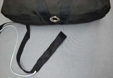
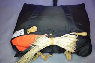
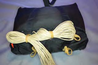
28. When packed, very little (if any) of the Trap System should be visible.
29. When re-packing the reserve, the Trap should be visually inspected.
Unless it has been used, there is no need to remove and reinstall the Trap Line.
If you have any further questions or concerns regarding proper care and packing of the Trap System, please contact Mirage Systems, Inc at 386-740-9222.
4/28/2016
16 – Installing The Main Parachute Canopy And Risers
It is recommended that the main parachute be installed by an appropriately rated Senior or Master parachute rigger.
Attach the main parachute risers to the harness release rings after the reserve parachute is assembled and packed.
If an RSL is installed on the reserve parachute, the main riser with the RSL connecting ring is installed on the wearer’s left.
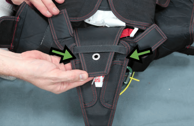
Note
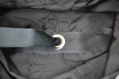
Main risers manufactured by Mirage Systems, Inc. have the RSL connecting ring mounted BELOW the 3-ring release grommet passing through the riser. Main risers are considered a “weak link” between the forces your main canopy can generate and your harness. Experience has proven that main risers can break at the riser grommet if subjected to a high G-load.
If the RSL connecting ring is installed above the riser grommet and that riser was to break, the reserve parachute could be deployed while the malfunctioning main parachute is still attached by the opposite riser. For this reason, main risers made by another manufacturer may not be compatible with your Mirage RSL.
Only install main risers with the RSL connecting ring mounted below the 3-ring release grommet passing through the riser. If the risers were not manufactured by Mirage Systems, Inc., check to make sure that the RSL is long enough to reach the connecting ring. Mirage risers are mandatory when the Trap system is installed.
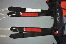
Thread the yellow release cables of the breakaway system through their respective housings and mate the hook velcro on the handle with the pile velcro located in the pocket. The handle should be positioned close to the cable housings so that very little yellow cable is showing between the handle and the ends of the housings.
CAUTION!
If an RSL is installed, verify that the exposed yellow release cable extending from the short housing end fitting is 5.75” long, and exposed yellow release cable extending from the long housing end fitting is 6.25” long.
When the release cables are withdrawn, the right riser MUST release BEFORE the left side riser with the RSL attached.
If an RSL is not installed, the length of the yellow release cable extending from the end fittings can be 6” (both sides).
The minimum length for any release cable is 5.5”, and the maximum is 6.25”.
Note
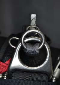
Each main riser has two rings. The larger ring on the end of the riser is referred to as the “middle ring” when the 3-ring release mechanism is assembled.
WARNING!
Main risers designed to be installed with the middle and small release rings to the rear of the risers could fail in an emergency situation and are not recommended!
Begin with either riser. Assembly is easier if the harness is positioned face up on a table or bench.
With the rings on the riser facing the front of the harness, pass the larger middle ring on the end of the riser through the release ring on the harness from the rear.
Fold the ring forward and up toward the small ring on the riser.
Pass the small ring through the middle ring from the rear and fold the small ring forward and up toward the grommet in the riser.
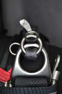
CAUTION!
Make sure that the small ring only passes through the middle ring!
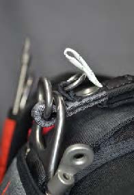
Thread the Type IIA loop over and through the small ring, then continue down through the riser grommet, exiting the grommet at the rear of the riser.
CAUTION!
Make sure that the Type IIA loop only passes through the small ring before entering the grommet!
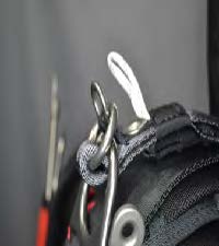
Making sure that there are no twists in the Type IIA loop, thread it through the end fitting on the release housing.
Pass the Type IIA loop through the end fitting from the long, flat side, and exiting on the cable housing side of the fitting.
The flat side of the end fitting must face the back of the riser.
Insert the yellow release cable through the Type IIA loop, making sure the loop isn’t twisted.
Be careful not to bend or kink the yellow cable when inserting it through the loop.
Insert the free end of the release cable into the protective housing installed on the rear of the riser, making sure that there are no kinks or loops in the cable between the loop and the housing.
Note
If using main risers not manufactured by Mirage Systems, Inc., it is recommended that the risers have flexible, metal protective housings for the yellow release cable ends.
Repeat the assembly process for the opposite riser.
Inspect both assembled 3-ring release mechanisms and, if used, attach the RSL quick release shackle to the connecting ring on the main riser.
Lay the Mirage out face down with the risers extended fully. The rear risers will be facing up.
Make sure that there are no twists in the risers.
Attach the main parachute canopy to the risers, making sure that the four line groups are routed to their correct riser.
Perform a thorough suspension line continuity check after installation.
Follow the main canopy manufacturer’s recommendations in using either Rapide Links or Slinks to attach the main canopy suspension lines to the risers.
When installing Rapide Links, the installation of vinyl tubing or fabric slider stops is recommended to prevent damage to the slider grommets.
Use a type recommended by the main canopy manufacturer.
Route the left and right main canopy steering lines through their corresponding guide rings on the rear main risers and attach the toggles to the steering lines in a manner recommended by the main canopy manufacturer.
Toggles are attached at the point marked on the steering lines by the canopy manufacturer.
Perform a continuity check after installation.
4/28/2016
17 – Installing The Main Deployment Bag And Pilot Chute
Collapsible Main Pilot Chute
The bridle of a standard collapsible main pilot chute is 7’ in length with the pilot chute permanently attached to the bridle.
Lengths of 9’ and 12’ are available options.
A curved pin, velcro tab, kill line window, and bag stop are sewn a short distance from the bag end of the bridle.
A kill line runs the length of the doubled bridle webbing, exiting between the two loops of the bag stop.
The exposed end of the kill line is sewn into the stitching forming the canopy end loop.
Thread the bag end bridle loop, exposed kill line, bridle retaining line and loop, and the two bag retaining loops through the grommet in the top of the deployment bag, from the outside in.
Thread both bag retaining loops onto the Rapide link with the exposed kill line and bridle retaining line and loop running through the center of the Rapide link.
Tighten Rapide link securely with the two bag retaining loops on opposite sides of the link.
Center the threaded barrel of the Rapide link inside one bag retaining loop.
Note – A Softlink may be substituted for the Rapide link.
Hold the bag end bridle loop open and pass the deployment bag, bridle, and pilot chute through it.
Cinch the resulting larks head knot tight on the canopy bridle loop.
Make sure the exposed kill line runs directly to the center of the bag retaining loops.
Non-Collapsible Main Pilot Chute
The bridle of a standard non-collapsible main pilot chute is 7’ in length and has a loop at each end.
A curved pin, a velcro tab, and bag stop are sewn a short distance from the bag end of the bridle.
Insert the pilot chute end of the bridle through the two pilot chute bridles.
Hold the pilot chute end loop open and pass the entire bridle through it.
Cinch the resulting larks head knot tight on the canopy bridle loops.
Thread the bag end bridle loop through the grommet in the top of the deployment bag, from the outside in.
Pass the bag end bridle loop through the canopy bridle attachment loop.
Hold the bag end bridle loop open and pass the deployment bag, bridle, and pilot chute through it.
Cinch the resulting larks head knot tight on the canopy bridle loop.
Pull Out Main Pilot Chute
The pull-out main pilot chute is available as a non-collapsible or collapsible version.
Both versions use the same removable pull-out handle with lanyard and straight pin.
NON-COLLAPSIBLE
The bridle of a standard non-collapsible pull-out main pilot chute is 7’ in length and has a loop at each end. A bag stop is sewn a short distance from the bag end of the bridle. It does not have a velcro tab or curved pin. Assemble the pilot chute and bridle in the same manner as any standard non-collapsible main pilot chute. Install the pull-out handle on the pilot chute by passing the small loop on the lanyard through the pilot chute bridle loops, then passing the entire handle, lanyard and pin through the loop, forming a larks head knot. Cinch the knot tight around the pilot chute bridle loops. Thread the bag end bridle loop through the grommet in the top of the deployment bag, from the outside in and install the bag, pilot chute, and pull-out handle on the main canopy bridle in the same manner as a standard non-collapsible main pilot chute.
COLLAPSIBLE
The bridle of a standard collapsible pull-out main pilot chute is 7’ in length with the pilot chute permanently attached to the bridle. Lengths of 9’ and 12’ are available options. A bag stop is sewn a short distance from the bag end of the bridle. A kill line runs the length of the doubled bridle webbing, exiting between the two loops of the bag stop. The exposed end of the kill line is sewn into the stitching forming the canopy end loop. There is no velcro patch, curved pin, or kill line window. Install the pull-out handle on the pilot chute by passing the small loop on the lanyard through the pilot chute bridle loops and the small loops on the ends of the pilot chute center lines, then passing the entire handle, lanyard and pin through the loop, forming a larks head knot. Cinch the knot tight around the pilot chute bridle loops.
CAUTION!
Make sure that the kill line is not captured in the larks head knot. The kill line must move freely after the larks head knot is cinched tight. Thread the bag end bridle loop through the grommet in the top of the deployment bag, from the outside in and attach the bag to the bridle with a Rapide Link in the same manner as a standard collapsible main pilot chute. Install the bag, pilot chute, and pull-out handle on the main canopy bridle in the same manner as a standard collapsible main pilot chute.
4/28/2016
18 – Packing The Main Parachute
Before attempting to pack your main parachute, complete a course of instruction in parachute packing.
Mirage Systems, Inc. does not recommend one method of folding the main parachute over another. We suggest that you follow the folding instructions provided by the canopy manufacturer, a rigger, or your instructor, until you gain experience in the method you prefer. If you are unclear about any of the procedures described here, ask your instructor or a rigger for assistance.
Inspect the main deployment bag and prepare it for packing by replacing any broken or missing stow bands. Mirage, Inc. does not recommend one type or size of line stow band over another. We suggest that you follow the recommendation made by the canopy manufacturer, a rigger, or your instructor, until you gain experience in the types of stow bands available and what you prefer.
Inspect the main pilot chute. Cock the kill line if using a collapsible main pilot chute.
Important!
If using a collapsible main pilot chute, it must be cocked before every jump. Failure to cock the pilot chute could result in a parachute malfunction! When cocked, a blue mark on the kill line will be showing in the window near the curved pin. Consult your instructor or a rigger if you do not understand how to cock the pilot chute and verify that it has been cocked correctly.
Optional
If using a collapsible main pilot chute, the bridle will have a loop of slack inside the deployment when the pilot chute is cocked. Use care to make sure this loop does not loop around any part of your main parachute canopy, as damage to the canopy fabric may result. Some owners have recommended using a very small rubber band attached to the Rapide® Link to fold and stow the excess bridle webbing.
Set the brakes and stow the excess brake lines in the keepers on your risers. Perform a suspension line continuity check.
Fold the main parachute canopy and place it into the deployment bag.
Be sure to long fold the canopy slightly wider than the deployment bag closing flap. This will ensure that the packed deployment bag completely fills all corners of the main parachute container.
There are three types of main deployment bags available for your Mirage G4.1. These are Standard, Split, and Semi-Stowless. The main difference between all three is how the suspension lines are stowed.
When the parachute canopy is in the deployment bag, close the bag by making the locking stows on the closing flap. Some deployment bags have three locking stows, and some have four, determined by the size of the deployment bag.
The length of each suspension line locking stow (bight) is a matter of personal preference. We recommend a length of 2” to 2-1/2” past the stow band for locking stows. Follow the recommendation made by the canopy manufacturer, a rigger, or your instructor, until you gain experience in the length of stows that work best for your canopy and deployment bag.
Standard Deployment Bag
If the bag has three locking stows, make the center locking stow first, then alternate left or right for the two outside locking stows.
If the bag has four locking stows, make the first locking stows in the center, left or right, then alternate left or right to the outside stows.
If you need help, have a rigger or experienced packer show you the proper sequence.
Stow the remainder of the lines alternating left or right until 12” to 15” (+/-) of lines remain between the last stow and the risers.
4/28/2016
18.1- Packing A Split Deployment Bag
Some small deployment bags are manufactured as split bags upon request. A split bag has a short notch added in the front of the bag with a cover flap and extra grommet. This allows the mouth of the bag to open larger.
The first locking stow is always made at the center notch.
If the deployment bag has three locking stows, pass the center stow band through the extra grommet on the notch cover flap, then through the grommet on the closing flap before making the first locking stow.
If the split bag has four locking stows, make first stow at either center grommet.
Make the remainder of the locking stows alternating left or right across the closing flap.
Stow the remainder of the lines in the same manner as a standard deployment bag, leaving 12” to 15” (+/-) between the last stow and the risers.
4/28/2016
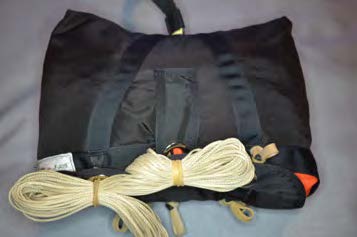
18.2 – Packing A Semi-Stowless Main Bag
A semi-stowless main deployment bag has three or four locking stows and a pouch to hold the remainder of the suspension lines, instead of additional line stow bands.
1. Fold the main parachute in accordance with the canopy manufacturer’s instructions and place in the deployment bag. Long fold the main parachute slightly wider than the closing flap of the bag.
2. Close the semi-stowless bag as you would any conventional bag by making the locking stows. Start in the center, then alternate left or right to the outside stows.
3. Roll packed bag toward main pilot chute, placing the line stow pocket facing up. Begin stowing suspension lines by making a large loop on top of one end pocket.
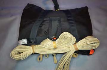
4. Form a “figure eight” pattern with the suspension lines on top of both end pockets. Make sure that suspension line loops are completely across bag.
5. Continue stowing the suspension lines in a figure eight pattern until the main risers are 15” (+/-) from the packed bag.

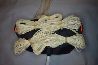
6. Lift the end pockets and place over the suspension line loops.
7. Close cover.
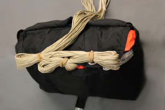
8. Insert tuck tabs into pockets. The suspension lines must enter and exit the pocket through the notch in cover.
9. Roll packed bag toward the risers and place in main container normally.
4/28/2016
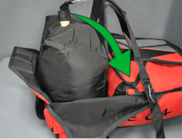
19 – Closing The Main Container
Lift the packed deployment bag over the reserve container and set it just below the main container.
Make sure not to twist or rotate the bag as you do this.
Stow the risers, left and right, alongside the reserve container.
Fold the secondary riser covers down over the stowed risers.
Fold the riser covers up over the risers and insert the riser tuck tabs in their pockets on the yoke.
Place the ends of the risers to the outer edges of the main container and spread them apart to reduce bulk in the center of the container.
Fold back the main container flaps and place the packed deployment bag into the pack tray, with the suspension lines down and the bridle up.
Lift up on the top flap and rotate the top of the bag toward the reserve container, while pushing it downward into the bottom of the main container.
Make sure the bag fills the bottom corners of the main container.
Roll and push the top of the bag down against the bottom of the packed reserve container.
With the bulk evenly distributed, the packed main container will have a smooth appearance.
Route the bridle on top of the bag and out the right side of the main container.
Inspect the main closing loop on the No. 1 flap and thread a pull-up cord through it.
Thread the pull-up cord through the grommet in the No. 2 flap and close the flap by pulling the pull-up cord toward the bottom of the main container until the closing loop is completely through the grommet.
Pushing up on the No. 1 flap while pulling downward on the pull-up cord can help.
Make sure the bridle is routed out from under the right side of the No. 2 flap.
Helpful Hint
Kneel on top of the No. 2 grommet and pull-up cord in the middle of the bag with one knee while preparing for the next step.
This will prevent the closing loop from withdrawing, keep air from expanding the bag, and help fill the corners of the main container.
Mate the 1” pile velcro on the bridle with the 1” hook velcro sewn to the No. 2 flap.
Again, route the bridle to the right.
Close the No. 3 flap by threading the pull-up cord through the grommet on the No. 3 flap and pulling to the right.
When you are ready to start pulling, lift your knee from the No. 2 flap, and when the closing loop is completely through the grommet, return your knee on top of the No. 3 grommet and closing loop.
Make sure that you don’t allow the packed bag to be pushed out the right side of the main container as you close the No. 3 flap.
Close the No. 4 flap by threading the pull-up cord through the grommet on the No. 4 flap and pulling to the left.
Make sure the bridle is routed upward from the velcro and away from the No. 4 flap.
When you are ready to start pulling, lift your knee from the No. 3 flap, and when the closing loop is completely through the grommet, insert the curved pin on the bridle through the closing loop.
Close the main pin cover.
Important!
- If using a collapsible main pilot chute, make sure the pilot chute is cocked by verifying that the blue mark on the kill line is showing in the bridle window near the curved pin.
- Do not exit the bridle out from under the left side of the No. 2 flap and back across the No. 2 flap left to right. This can result in a slow opening or a pilot chute-in-tow malfunction. A label is sewn inside the main pin cover flap showing a diagram of the standard bridle routing.
- With the standard bridle routing, curved pin direction, inserted up or down, is a matter of personal preference.
- Always get a pin check before each jump when boarding the aircraft.
Alternate Bridle Routing
Note – An alternate bridle routing sequence has been tested and may be used if desired. Consult with your instructor or a rigger before attempting.
Route the bridle directly from the top of the bag down to the lower right.
Do not mate the 1” velcro on the bridle with the 1” hook velcro on the No. 2 flap.
Pull the closing loop through the No. 2 flap.

Close the number 3 flap.
Close the No. 4 flap over the bridle with the bridle exiting the main container from under the No. 4 flap on the bottom right.
Verify that a collapsible pilot chute is cocked, then fold the bridle webbing in half away from the curved pin and pin the closing loop.
Push the excess bridle back under the No. 4 flap, making sure that there is plenty of slack between the top of the deployment bag and the curved pin to allow the pin to be extracted by the pilot chute.
The end of the curved pin will be facing the top of the main container.
Tuck the remaining bridle under the bottom edge of the closed No. 4 flap, working your way from the center to the bottom corner of the main container, in preparation for folding the main pilot chute.
Route the bridle to the lower left and reverse flaps 3 and 4 if using a left side BOC.
Close the main pin cover.
No bridle should be exposed.
4/28/2016
19.1 – Folding The Main Pilot Chute
There are several methods of folding the main pilot chute. Mirage Systems, Inc. does not recommend one method over another. We suggest that you follow the folding instructions recommended by your instructor or a rigger, until you gain experience in the method you prefer.
If you are unclear about any of the procedures described here, ask your instructor or a rigger for assistance.
Spread the pilot chute canopy out with the mesh up. Fold the canopy in half at the handle, with the fold parallel to the longest portion of the handle.
The bridle should exit the bottom between the folds.
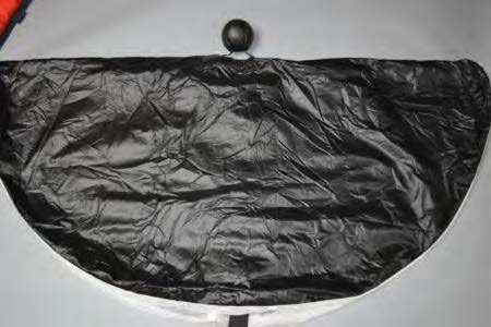
Make a second fold parallel to the first by folding the edges up toward the handle, making the folded pilot chute approximately the length of the spandex pouch.
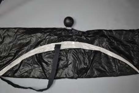
S-fold the bridle on top of the canopy folds just under the handle until about 8” of the bridle remains unfolded from the canopy to the bottom corner of the main container.
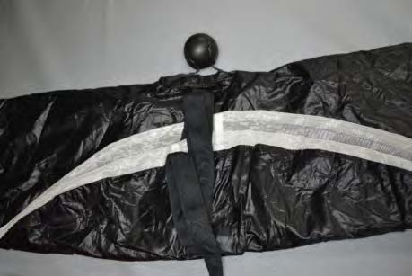
Fold the ends of the folded canopy to the center, until the folded pilot chute is approximately 4” wide.
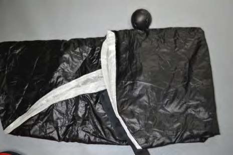
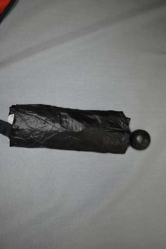
Insert the folded pilot chute into the spandex pouch.
No bridle or main pilot chute material should be exposed when the pilot chute is properly stowed.
Any exposed bridle or pilot chute could result in a premature deployment.
If the pilot chute is equipped with a freefly tab, insert the tab under the edge of the right main container flap.
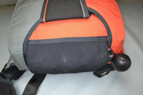
4/28/2016
20 – Pullout Pilot Chute Packing Instructions
1. A strip of binding tape is installed on the top of collapsible pull-out main pilot chutes to aid in cocking the pilot chute.
CAUTION! – Collapsible pull-out main pilot chute bridles do not have a window to verify that the kill line is cocked.
If you are unclear about any of the procedures described here, ask your instructor or a rigger for assistance.
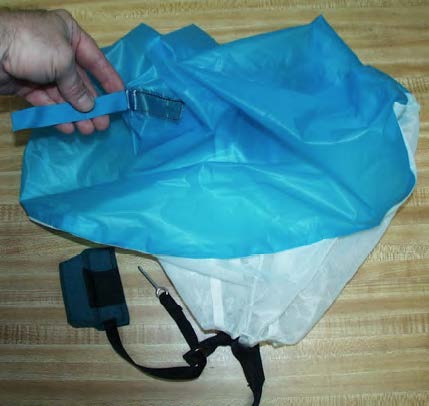
2. After placing the main canopy in the container, remove all twists in the bridle, and check that the pilot is cocked.
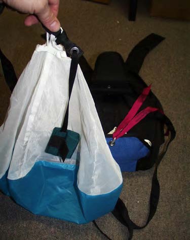
3. Prior to closing flaps 1 and 2, insert the handle freefly tab under the edge of the main container flap, as shown.
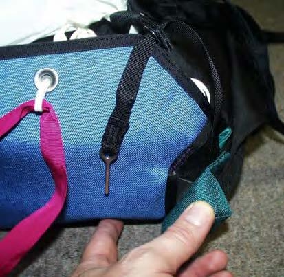
4. Neatly fold the bridle and place on center of the main deployment bag.
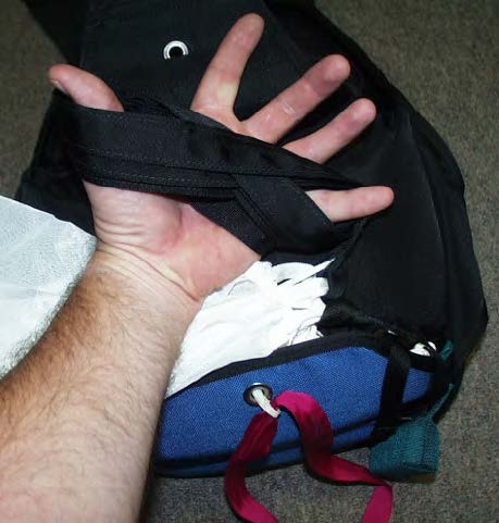
5. Place bridle under pilot chute.
Place pilot chute bridle attachment at the bottom right side of container (for right-handed user).
Make sure grommet tab is extending out of container on top of bottom flap.
Pin lanyard must move freely through grommet.
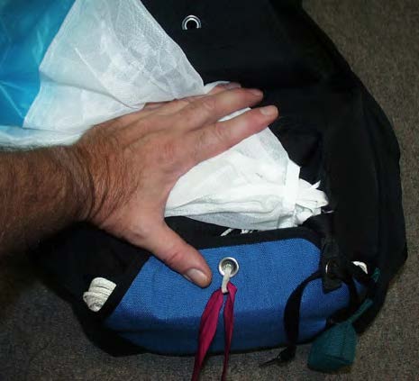
6. Fold the pilot chute canopy back over mesh and close flaps 1 and 2.
Important – Make sure the pin lanyard runs directly from the straight pin to handle through the tab grommet.
Tab must remain in bottom corner of container, as shown.
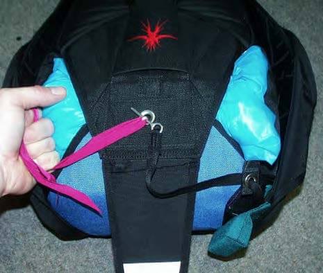
7. Close flaps 3 and 4.
Important – Make sure the grommet tab remains in bottom right corner and is free to pop down easily as shown.
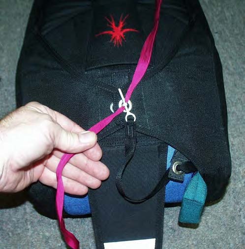
8. Tuck lanyard and tab under the side flap and close pin cover.
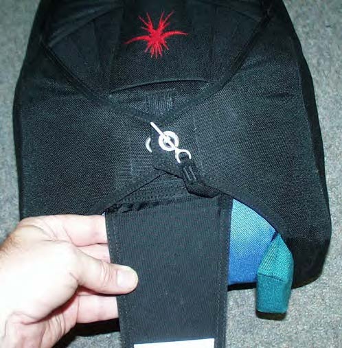
CAUTION!
Get instruction if you have never packed or used a pull-out pilot chute.
Practice deploying the main parachute on the ground.
4/28/2016
21 – Maintaining Your Mirage
Your Mirage will function correctly, look better, and last longer if maintained properly. Like any piece of sporting equipment that is subject to wear and tear, it will last longer with routine maintenance.
Inspect Your Mirage Regularly
It is a good idea to inspect it before each use. It only takes a few minutes to inspect it for any obvious signs of damage, contamination or unusual wear. Check the entire outside, front and rear.
Each time the main parachute is repacked, the canopy, suspension lines, deployment bag, pilot chute, bridle, risers and toggles should be inspected by the packer.
Once a month, examine the rig closely, making note of every detail. Small problems can turn into costly repairs if not corrected early. Delaying repairs could result in further damage, or even a malfunction.
Report any minor problems to your rigger before they become major. Never attempt to repair any problems yourself, unless you are a certified rigger.
Your rigger is responsible for determining the airworthiness of the entire approved assembly when he/she repacks the reserve parachute. The approved assembly part of your Mirage is everything except the main parachute and its components. This is an important part of maintaining the safety and reliability of your Mirage, and is accomplished every 180 days in the U.S.
If you have any concerns about your main parachute, talk to your rigger. He/she can answer your questions and probably perform any required maintenance.
Pay Attention To These Items When Inspecting Your Mirage
- Breakaway System – Inspect the 3-Ring release mechanism, which includes the harness rings and main risers, the release handle with cables, and the release housings. Check for proper assembly, damage or wear. Pay particular attention to the Type IIA fabric loops on the main risers and the condition of the yellow release cables. Refer to the 3-Ring Release Maintenance instructions at the end of this section for detailed inspection requirements.
- Reserve System – You obviously can’t inspect what is inside your reserve container, unless you are a certified rigger. However, there are several critical checks on the outside of your reserve that you should get in the habit of making.
- Check the reserve ripcord handle and exposed cable for any sign of damage.
- Check to make sure the ripcord pin is properly seated and not bent.
- Make sure the ripcord pin and grommet are free of soil or debris.
- Make sure the ripcord pin protector flap is secure.
- If installed, check the RSL and quick-disconnect snap shackle, and check the stitching securing the RSL guide rings for broken stitching. Make sure the ripcord cable passes through the first guide ring, the RSL ring, then the second guide ring.
- Check the reserve closing loop for fraying or wear.
- Check the packing data card to determine if the reserve repack is in date, and check to make sure the rigger’s seal is in place and not broken.
CAUTION! – Report a frayed closing loop immediately to your rigger! Never jump your Mirage if the reserve closing loop is frayed. A frayed closing loop could break which would immediately deploy your reserve parachute!
- Harness – Check the harness for signs of contamination, abrasion, cut or frayed webbing, and broken stitches. Check the metal hardware for abrasion or corrosion.
- Main Container – Check for damage, wear, or broken stitches.
- Check plastic stiffeners and replace any that are broken.
- Check the velcro tab that retains the bridle for broken stitches.
- Check grommets, and have any replaced that may be damaged or pulling out of their setting.
- Check the condition of the spandex pilot chute pouch and replace if torn or worn out. A loose pouch could lead to a premature deployment of the main parachute.
- Check the main closing loop and replace if frayed.
- Main Pilot Chute – Check for any signs of torn fabric or broken stitches.
- Check the bartacks that secure the handle to the canopy for broken stitches.
- Check the bartacks securing the centerline to the canopy and the bridle.
- If collapsible, check the condition of the kill line.
- Inspect the bridle for damage, frayed webbing, or broken stitches.
- Check the curved pin for damage, or corrosion and security of attachment to the bridle. Replace if bent. Do not attempt to straighten a bent pin.
- Repair or replace pilot chute if mesh is torn. Some separation of the weave of the mesh is normal with use.
- Automatic Activation Device (Optional) – Inspect according to the AAD manufacturer’s instructions.
Cleaning
What To Avoid
Most of the fabric used to manufacture your Mirage is nylon. While nylon is a very durable material that is easy to care for, it can be damaged like anything else. You need to be aware of what will harm your Mirage. Repairs can be very expensive.
- Sunlight – The ultraviolet rays in sunlight can quickly fade and permanently weaken nylon. Keep your Mirage out of direct sunlight when not in use. Remember that ultraviolet radiation from incandescent lighting can cause damage also.
- Heat – Excessive heat can damage nylon. Avoid storing your Mirage near any heat sources such as lamps, radiant heaters, or running machinery.
- Acids – Nylon, like most other fabrics, is easily damaged by a variety of acids. Keep your Mirage away from hangar floors and dirty car trunks, or similar places where acids may be present. Acid can quickly damage many layers of nylon if left unnoticed. If contamination occurs, try to isolate the damaged area from the rest of your Mirage and immediately neutralize the acid with baking soda and water if readily available. If not, thoroughly rinse with warm, soapy water or plain water. If acid contamination is suspected, a rigger must thoroughly inspect your Mirage to look for hidden damage. When not in use, it is always a good idea to keep your Mirage in a rugged canvas bag or plastic bin. While a heavy nylon or canvas bag is helpful in protecting your Mirage from dust and dirt, it won’t prevent acid from destroying your Mirage. A plastic bin in the trunk of your car could save you hundreds of dollars in repair charges.
- Oils and Grease – Most petroleum products do not damage nylon. They simply stain it. Your rigger may be able to remove some petroleum stains with dry cleaning fluid. Others, like grease, are very difficult to remove and some stubborn stains may be impossible to remove completely. Your rigger can check with a local professional cleaner for advice.
- Water – Water will not structurally damage nylon, but it can cause some fabric and tape colors to run or bleed onto lighter adjacent materials. Some parts of your Mirage may shrink. Moisture promotes mildew, which can permanently stain fabric. Sea water immersion should be avoided, as it can corrode some components and even rust “stainless steel” hardware if not thoroughly rinsed out by a prolonged soaking in fresh water. If exposed to sea water, notify your rigger immediately. The rig will need to be completely disassembled to make sure that all components can be thoroughly rinsed. The AAD (if installed) will need to be removed and be serviced. Perspiration can cause damage similar to sea water, but on a smaller scale. If you jump in a hot climate, consider washing your Mirage occasionally.
- Soil – Soil, or “dirt”, may damage your Mirage. The sand and grit in soil can be abrasive to nylon materials. Brush off soil with a soft brush when dry, and wash soiled area. Check to make sure that soil is cleaned from the ripcord housing and ripcord pin, reserve container grommets, and 3-ring release rings and housings. Soil inside of webbing around metal hardware can be abrasive. Consult your rigger if heavily soiled.
- Sand – Fine sand can weaken and cut webbing and fabric and prolonged exposure to fine sand can shorten the life of the entire assembly. Fine sand on webbing can cause slipping through hardware. It is recommended that your Mirage be washed every 500 jumps to remove sand if used in a desert climate.
- Abrasion – Nylon frays quickly when dragged across concrete or other rough surfaces. Always pack your Mirage on a clean, covered surface, such as carpet. Do not drag your Mirage on concrete when packing the main parachute. Always have your rigger examine your Mirage if you slid on a rough surface, or if dragged due to the wind. If you slide to a stop on landing, have your rigger check for damage to your leg straps.
Cleaning
Cleaning your Mirage occasionally may make it look better, but there are some things to keep in mind before you toss your Mirage into the bathtub:
Clean your Mirage only when it needs it. Like a new shirt, it is going to change in some way each time you wash it. Some colors will fade, some colors can run, and some parts may shrink.
All stains cannot be removed. Ground-in dirt, grass stains, or blood are extremely difficult to remove completely. Don’t wash your Mirage expecting it to look “like new” when it comes out of the wash.
Your Mirage may last longer if you wash it. If you jump in a hot, dusty location, washing your Mirage will remove abrasive sand or dust and help prevent fraying of the webbing around the hardware. Washing will also remove salt residue from perspiration that can cause corrosion or rusting of the hardware.
A dry cleaning solvent such as MEK or naptha can be used to spot clean small areas of oil or grease. Check a small area for colorfastness before attempting, as some solvents can cause the color to run. Consult with a local professional cleaner before using.
Use a soft brush to remove surface dust and dirt. Washing your Mirage can cause the fabric to fade and some parts to shrink, so wash it only when needed. Wash it gently with a mild detergent like Woolite ®, Ivory Liquid®, or a similar detergent. Wash in cold water and use a soft brush. Do not use bleach or harsh chemical cleaners. Squeeze, but do not wring the fabric to remove excess water. Air dry only, which can take several days.
3 Ring Release Maintenance
3-Ring Release Maintenance
The 3-ring release is a simple and reliable mechanism that allows a skydiver to quickly jettison a malfunctioning main parachute. In use for years with excellent results, it is one of the foremost safety advances in skydiving equipment to date. Like all skydiving gear, the 3-ring release should be carefully inspected and tested regularly.
Anytime 3-ring release mechanisms are subjected to abuse, such as abrasion from dragging across a runway, it is important that a complete inspection be performed prior to the next jump.
It is also important to keep the mechanism clean at all times. Mud, dirt, and dust can clog housings, damage components, and adversely affect the reliability. If your Mirage becomes immersed in mud or muddy water, clean the mechanisms with mild soap and warm water, and dry thoroughly before use.
To ensure reliability in an emergency situation, operate the 3-ring release mechanism at least once a month while on the ground and inspect the components thoroughly. Inspect more frequently in humid, muddy, desert or freezing climates.
Monthly Reliability Checks:
- If an RSL is installed, begin by disconnecting the quick disconnect snap shackle from the left main riser, then pull the release/cutaway handle to extract the release cables completely from their housings.
- Tug on the main risers to unfold the two small release rings and disconnect them from the large release rings on the harness.
- Flex the risers – When disconnected from the harness, vigorously twist and flex the webbing of the risers where the two smaller release rings are attached. This will help remove the natural tendency of the webbing to “set”, or deform, from use.
- Check the grommets that the Type IIA loop passes through for burrs or sharp edges.
- Check the Type IIA fabric loops – Carefully examine the two loops for wear, abrasion and cleanliness. Check the security of the stitching attaching the Type IIA loops to the main risers. Flex the Type IIA loops to help remove the “set”.
- Check the housings on the back of the risers for damage and security of the stitching.
- Inspect for wear – Closely inspect all components for any signs of wear or damage.
Note – It is normal for release rings to develop small dings and dents due to the opening forces generated by the main parachute. As long as no sharp burrs are present, small dings and dents can be ignored.
- Check the stitching – Check the security of all stitching holding the small release rings to the main risers, and check the security of stitching holding the release rings to the harness.
- Check the cables – Inspect the yellow release cables for kinks, burrs, nicks, or any irregularities, paying particular attention to the last few inches of the cables that pass through the Type IIA loops. Inspect the ends of the cables. The cables are finished at the factory with a smooth, rounded end. Before re-installing, clean and lubricate the cables with a dry, clean cloth and spray silicone. Refer to the “Installing a Replacement Cutaway Handle ” in this section for complete installation details.
- Check the handle – Inspect the release/cutaway handle for wear, damage, open seams or broken stitches. Inspect the stitching that secures the hook velcro to the handle. Check to make sure that the plastic insert and stiffening tab are not broken.
- Check the pocket – Check the release handle pocket on the harness for the condition of the pile velcro. If it is excessively fuzzed and does not hold the release handle securely in place, have a master rigger change it.
- Check the housings – Check cable housings for dents, kinks, and corrosion. Check the highstrength end fittings for burrs or sharp edges. Each should have a dimple securing it to the end of the housing. Check the handle ends of the housings for corrosion or burrs. Check the security of the clamps holding the ends of the housings in place.
Installing A Replacement Cutaway Handle
Installing A Replacement Cutaway Handle
The cutaway handle originally delivered with your Mirage had the cable length trimmed specifically for your rig.
The overall length of the cables varies according to the harness and container size.
Mirage Systems, Inc., recommends that a qualified rigger install the replacement cutaway handle for you in accordance with the following instructions:
Tools Needed:
- A ruler
- A clean soft cloth
- Spray silicone lubricant*
- Sharp wire cutters
- Matches or cigarette lighter
* A dry lubricant, such as powdered graphite, may be used if desired. Use caution, however, since powdered graphite is messy and the stains can’t be removed from your rig.
Clean and lubricate the yellow cables
Before installing the yellow release cables, apply a small amount of spray silicone to a soft cloth and wipe the entire length of both cables.
Be sure to remove any excess lubricant by wiping the cables with a clean, soft cloth.
Position end fittings
Before installing the release cables, check to make sure that the end fittings are positioned correctly, and that the housings are “at rest”, without any tension on them.
The base of the end fitting on the long housing should be about even (+/-) with the top of the harness release ring.
IMPORTANT!
Make sure that there is no sand or grit on the cables when threading the cables through the release housings.
Install cables
Thread both cleaned and lubricated yellow release cables of the breakaway system through their respective housings and mate the hook velcro on the handle with the pile velcro located in the pocket.
The handle should be positioned close to the cable housings so that very little yellow cable is showing between the handle and the ends of the housings.
Mark cables for cutting
Measuring the cables from where they exit the end fittings, we recommend that you mark the cables at:
- For non-RSL equipped rigs, 6” (both sides).
- For RSL equipped rigs, 6.25” for the RSL side, and 5.75” for the NON-RSL side.
- The minimum length for any cable is 5.5”, and the maximum is 6.25”.
Double check your marks
Before cutting, we recommend that the handle be removed from the pocket and the release cables be slowly withdrawn to check your measurements.
When the mark on the non-RSL side cable reaches the bottom edge of the hole in the end fitting, the RSL side cable should extend 1/4″ to 1/2″ past the end of its end fitting.
If not, reposition the handle in the pocket and double-check your measurements.
CAUTION!
If an RSL is installed, the RSL side cable MUST release last!
If an RSL is installed, verify that the exposed yellow release cable extending from the short housing is shorter than the exposed yellow cable extending from the long housing. The left riser with the RSL attached MUST release AFTER the right riser releases when the cables are withdrawn.
Cut the cables
When you are satisfied that the cables are marked correctly, cut each cable at your marks with sharp wire cutters.
Finish the ends of the cables
After cutting, finish the ends to cover the exposed inner steel cable.
Using a lighter or matches, warm the yellow plastic coating for 5 seconds to soften it.
Hold the end of the cable at the edge of the flame, but not in the flame.
Remove the flame and quickly pull and roll the yellow plastic coating with your fingers over the end of the exposed steel cable.
Make sure that no cable remains exposed, and that there are no burrs or snags.
Reheat very briefly if needed to shape the ends.
CAUTION!
Heating the cable ends too long can result in injury! Heat only long enough to soften the yellow covering, not melt it or set it on fire!
Repairs
Repairs
Every part used to construct your Mirage could be replaced if required. Some are easy to change, and some require major reconstruction of the rig.
Depending upon what is being repaired and how the repair must be accomplished determines if the repair is considered to be a major or minor repair.
Minor Repairs
The following parts can be ordered as replacements or spares and are easily changed by a Senior or Master Parachute Rigger.
Replacing any of these parts with a factory made replacement part is considered a minor repair, and may be accomplished by an appropriately rated Senior or Master Parachute Rigger, or a foreign equivalent.
- Main Deployment Bag
- Main Pilot Chute
- Main Risers
- Main Toggles
- Main Closing Loop
- Main Cutaway Handle / 3-Ring Release Handle and Cables
- Reserve Deployment Bag
- Reserve Deployment Bag Safety Stow
- Reserve Pilot Chute
- Reserve Ripcord
- Reserve Toggles
- Reserve Closing Loop And Disc
- RSL Lanyard*
- Leg Pads
- Leg Pad Bungee
- Lumbar Support Strap
- Harness Webbing Keepers
* Replacing the RSL guide rings on the No. 6 flap is considered a major repair. When ordering any of these parts, the serial number of the Mirage is required to make sure that we send the correct item. Some items also require a length and/or color. Contact Mirage Systems, Inc. for guidance.
Major Repairs
Major repairs to your Mirage are authorized if accomplished by an appropriately rated Master Parachute Rigger, or a foreign equivalent. Repairs made to installed parts must return the part to an airworthy condition without altering the design, configuration, materials used, or construction techniques.
The replacement of the following parts is considered a major repair and require the expertise of an appropriately rated Master Parachute Rigger or a foreign equivalent to install. Riggers are encouraged to order replacement parts from Mirage Systems, Inc., rather that trying to make the parts locally. Mirage Systems, Inc. maintains the patterns for all parts made after 1998.
The parts on this list are available from Mirage Systems, Inc.
Any part of the harness webbing
Any part of the harness hardware
Any part of the reserve container
Any part of the main container
Any part of the back pad and yoke
Release assembly housings
Reserve ripcord housing
When ordering parts, you will need to provide the model (G3, G4.1, RTS), size (MZS, M5, etc.), and serial number of the Mirage. Some items also require additional information.
Alterations
Alterations are changes made to the original design configuration of an approved parachute assembly.
Repairing a Mirage in a manner that does not duplicate the original design, configuration, materials used, and construction techniques, is an alteration.
Alterations to the design of a Mirage are NOT AUTHORIZED, and void the TSO approval.
Cleaning
9/28/2018
22 – User Instructions
Putting On Your Mirage
Putting your Mirage on properly will ensure a proper fit each time you use it. Here is a suggested way to put it on.
You will develop your own method, but the key to a proper fit is leaning far forward while tightening the leg straps (step 5, below), and not tightening the chest strap until standing upright.
IMPORTANT!
Make sure that you always thread the webbing of the leg straps and the chest strap through the friction adjusters correctly. Get assistance from an instructor or a rigger if you are in doubt.
1. To begin, loosen or undo both leg strap adjusters and undo the chest strap adjuster.
2. If you choose not to undo the leg straps, step through the leg straps and lift the rig behind you. Slip your left arm and shoulder through the left side of the harness yoke and let the rig hang on your left shoulder. Donning the left side first helps to prevent accidentally pulling the reserve ripcord.
3. Slip your right arm and shoulder through the right side of the harness yoke so that the rig is now resting on both shoulders.
4. Thread the chest strap through the adjuster, but do not tighten yet.
5. This step is important: Bend over forward and slide the rig toward your neck until it touches. While bent over, tighten both leg straps until the leg straps are comfortable. The leg pad ends should be close together. If you try to tighten the leg straps while standing upright, the weight of the rig hanging on the shoulders tends to prevent proper tightening.
6. Stand upright and tighten the chest strap only enough that the harness straps above the chest strap are parallel. Don’t over tighten!
7. Stow excess leg strap and chest strap webbing.
Adjusting The Elastic Lumbar Support
The Elastic Lumbar Support is standard on all Mirage G4.1s. It consists of elastic webbing, two rings, an adjuster, and a center comfort pad. It’s purpose is to aid in keeping the bottom of the main container and the hip rings closer together while “sit-flying”, much the same as a bungee cord helps keep the leg pads together. Use the adjuster located under the center comfort pad to shorten or lengthen the elastic webbing, as required. The webbing should be adjusted so that the elastic webbing will be stretched slightly when the leg strap adjusters are tightened.
Note
The Lumbar Support IS NOT A STRUCTURAL PART OF YOUR HARNESS! Do not attempt to use the Elastic Lumbar Support to overcome a problem with the fit of your harness. If you over-tighten it, it will break!
If you have concerns about the fit of your harness, contact Mirage Systems, Inc.
4/28/2016
23 – Installing Swoop & Sit Fly Belly Bands
For installation of optional swoop (large) & sit fly (small) belly bands on Mirage harnesses having hip rings.
1. Position adjuster end of belly band at left hip ring with the shorter loop on the inside of harness.
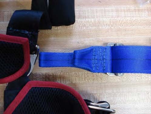
2. Fold long end through hip ring.
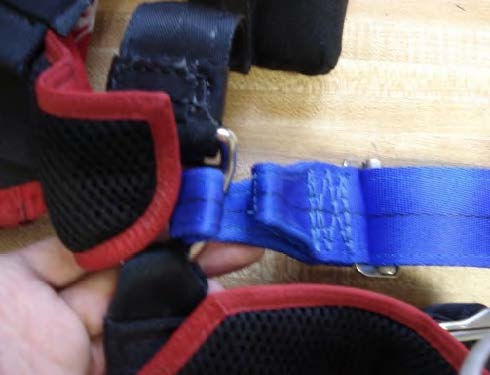
3. With red slink tab facing the leg straps, pass loop end of slink up through one webbing loop, and back down through the other.
Safety Note – The slink must pass through both webbing loops twice.
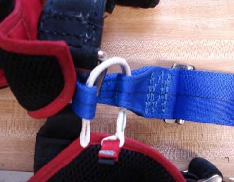
4. Pass loop end of the slink back through the first webbing loop.
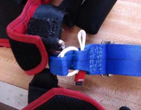
5. Pass the loop end of the slink back down through second webbing loop.
Pull slink tight.
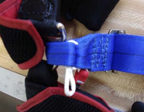
6. Pass loop end of slink through opening under red tab.
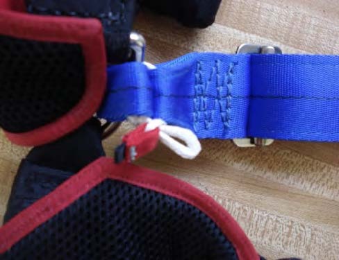
7. Pass red tab through loop end of slink.
Pull tight.
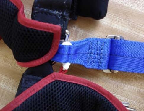
8. Repeat procedure for right hip ring.
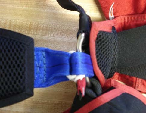
9. Properly installed, the adjuster will be on the wearer’s left and slinks will be to inside of harness.
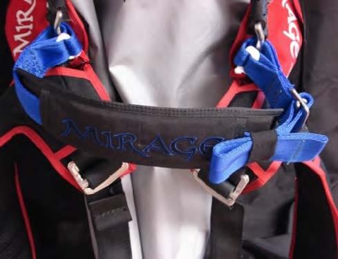
4/28/2016
24 – Installing Main Risers With Large Swoop Loops
Mirage main risers with large swoop loops are designed with Spectra line at the top of the front risers handle.
This allows the handle to lay flat when packed into the rig.
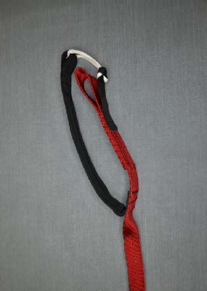
1.Make sure that the four line groups are routed to their correct riser.
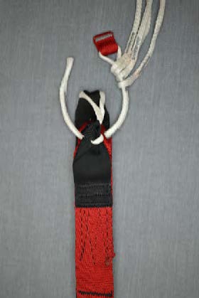
2. Pass slink through riser and line group a second time.
Make sure the slink passes around the Spectra line of the swoop loop.
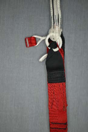
3. Pass loop end through under tab.
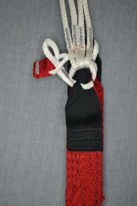
4. Feed tab back through loop and pull tight.
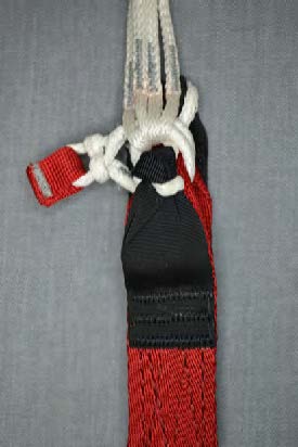
5. Tuck tab away.
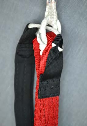
Perform a thorough suspension line continuity check.
4/28/2016