


G4 Owner’s Manual – 16 – Installing The Main Parachute Canopy And Risers
It is recommended that the main parachute be installed by an appropriately rated Senior or Master parachute rigger.
Attach the main parachute risers to the harness release rings after the reserve parachute is assembled and packed.
If an RSL is installed on the reserve parachute, the main riser with the RSL connecting ring is installed on the wearer’s left.
Note
Main risers manufactured by Mirage Systems, Inc. have the RSL connecting ring mounted BELOW the 3-ring release grommet passing through the riser. Main risers are considered a “weak link” between the forces your main canopy can generate and your harness. Experience has proven that main risers can break at the riser grommet if subjected to a high G-load.
If the RSL connecting ring is installed above the riser grommet and that riser was to break, the reserve parachute could be deployed while the malfunctioning main parachute is still attached by the opposite riser. For this reason, main risers made by another manufacturer may not be compatible with your Mirage RSL.
Only install main risers with the RSL connecting ring mounted below the 3-ring release grommet passing through the riser. If the risers were not manufactured by Mirage Systems, Inc., check to make sure that the RSL is long enough to reach the connecting ring. Mirage risers are mandatory when the Trap system is installed.
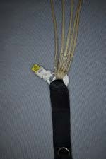
Thread the yellow release cables of the breakaway system through their respective housings and mate the hook velcro on the handle with the pile velcro located in the pocket. The handle should be positioned close to the cable housings so that very little yellow cable is showing between the handle and the ends of the housings.
CAUTION!
If an RSL is installed, verify that the exposed yellow release cable extending from the short housing end fitting is 5.75” long, and exposed yellow release cable extending from the long housing end fitting is 6.25” long.
When the release cables are withdrawn, the right riser MUST release BEFORE the left side riser with the RSL attached.
If an RSL is not installed, the length of the yellow release cable extending from the end fittings can be 6” (both sides).
The minimum length for any release cable is 5.5”, and the maximum is 6.25”.
Note
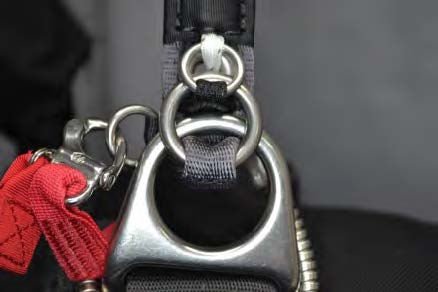
Each main riser has two rings. The larger ring on the end of the riser is referred to as the “middle ring” when the 3-ring release mechanism is assembled.
WARNING!
Main risers designed to be installed with the middle and small release rings to the rear of the risers could fail in an emergency situation and are not recommended!
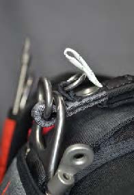
Begin with either riser. Assembly is easier if the harness is positioned face up on a table or bench.
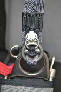
With the rings on the riser facing the front of the harness, pass the larger middle ring on the end of the riser through the release ring on the harness from the rear.
Fold the ring forward and up toward the small ring on the riser.
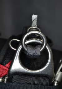
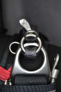
Pass the small ring through the middle ring from the rear and fold the small ring forward and up toward the grommet in the riser.
CAUTION!
Make sure that the small ring only passes through the middle ring!
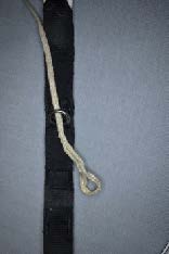
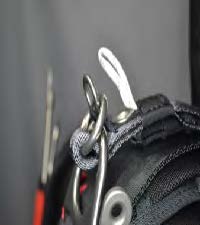
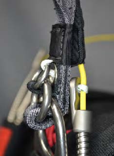
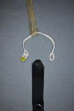
Thread the Type IIA loop over and through the small ring, then continue down through the riser grommet, exiting the grommet at the rear of the riser.
CAUTION!
Make sure that the Type IIA loop only passes through the small ring before entering the grommet!
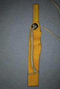
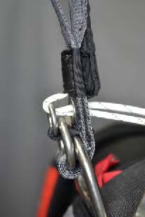
Making sure that there are no twists in the Type IIA loop, thread it through the end fitting on the release housing.
Pass the Type IIA loop through the end fitting from the long, flat side, and exiting on the cable housing side of the fitting.
The flat side of the end fitting must face the back of the riser.
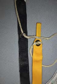
Insert the yellow release cable through the Type IIA loop, making sure the loop isn’t twisted.
Be careful not to bend or kink the yellow cable when inserting it through the loop.
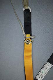
Insert the free end of the release cable into the protective housing installed on the rear of the riser, making sure that there are no kinks or loops in the cable between the loop and the housing.
Note
If using main risers not manufactured by Mirage Systems, Inc., it is recommended that the risers have flexible, metal protective housings for the yellow release cable ends.
Repeat the assembly process for the opposite riser.
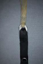
Inspect both assembled 3-ring release mechanisms and, if used, attach the RSL quick release shackle to the connecting ring on the main riser.
Lay the Mirage out face down with the risers extended fully. The rear risers will be facing up.
Make sure that there are no twists in the risers.
Attach the main parachute canopy to the risers, making sure that the four line groups are routed to their correct riser.
Perform a thorough suspension line continuity check after installation.
Follow the main canopy manufacturer’s recommendations in using either Rapide Links or Slinks to attach the main canopy suspension lines to the risers.
When installing Rapide Links, the installation of vinyl tubing or fabric slider stops is recommended to prevent damage to the slider grommets.
Use a type recommended by the main canopy manufacturer.
Route the left and right main canopy steering lines through their corresponding guide rings on the rear main risers and attach the toggles to the steering lines in a manner recommended by the main canopy manufacturer.
Toggles are attached at the point marked on the steering lines by the canopy manufacturer.
Perform a continuity check after installation.